Chapter 13
| Basic Administration Protocols
Ethernet Ring Protection Switching
– 466 –
Interconnection nodes C and D have separate ERP Control Processes for each
Ethernet Ring.
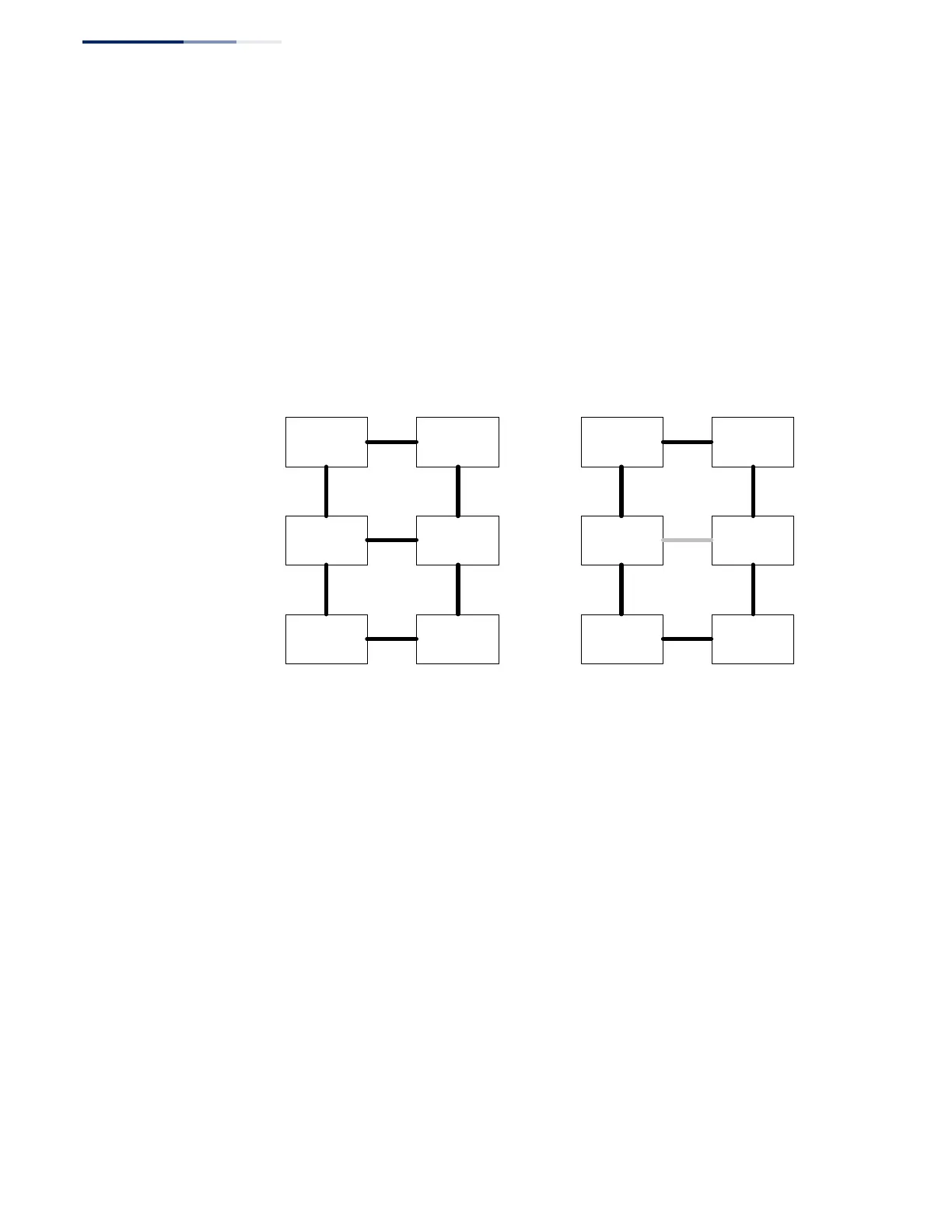
Figure 293 on page 466 (Signal Fail Condition) illustrates a situation where
protection switching has occurred due to an SF condition on the ring link between
interconnection nodes C and D. The failure of this ring link triggers protection only
on the ring to which it belongs, in this case ERP1. The traffic and R-APS channels are
blocked bi-directionally on the ports where the failure is detected and bi-
directionally unblocked at the RPL connection point on ERP1. The traffic channels
remain bi-directionally blocked at the RPL connection point on ERP2. This prevents
the formation of a loop.
Figure 293:
Ring Interconnection Architecture (Multi-ring/Ladder Network)
Configuration Guidelines for ERPS
1. Create an ERPS ring (Configure Domain – Add): The ring name is used as an
index in the G.8032 database.
2. Configure the east and west interfaces (Configure Domain – Configure Details):
Each node on the ring connects to it through two ring ports. Configure one
port connected to the next node in the ring to the east (or clockwise direction)
and another port facing west in the ring.
3. Configure the RPL owner (Configure Domain – Configure Details): Configure
one node in the ring as the Ring Protection Link (RPL) owner. When this switch
is configured as the RPL owner, the west ring port is set as being connected to
the RPL. Under normal operations (Idle state), the RPL is blocked to ensure that
a loop cannot form in the ring. If a signal failure brings down any other link in
the ring, the RPL will be unblocked (Protection state) to ensure proper
connectivity among all ring nodes until the failure is recovered.
4. Configure ERPS timers (Configure Domain – Configure Details): Set the Guard
timer to prevent ring nodes from receiving outdated R-APS messages, the
Hold-off timer to filter out intermittent link faults, and the WTR timer to verify
ring node Aring node B
ring node C ring node D
ring node F ring node E
ERP1
ERP2
RPL
RPL
RPL Owner
Node
for ERP1
RPL Owner
Node
for ERP2
ring link
(ERP1)
ring node Aring node B
ring node C ring node D
ring node F ring node E
ERP1
ERP2
RPL
RPL
RPL Owner
Node
for ERP1
RPL Owner
Node
for ERP2
ring link
(ERP1)
FAILURE
Normal Condition Signal Fail Condition