Chapter 13
| Basic Administration Protocols
Ethernet Ring Protection Switching
– 465 –
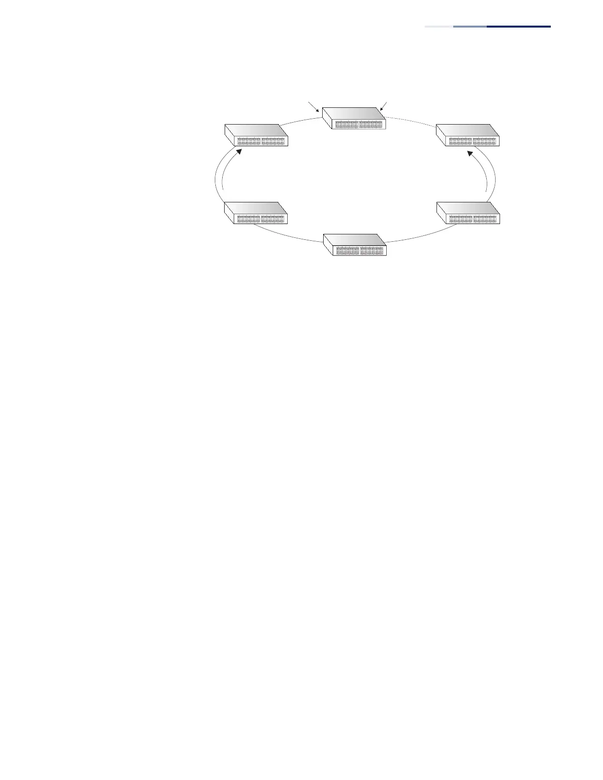
Figure 292: ERPS Ring Components
Multi-ring/Ladder Network – ERPSv2 also supports multipoint-to-multipoint
connectivity within interconnected rings, called a “multi-ring/ladder network”
topology. This arrangement consists of conjoined rings connected by one or more
interconnection points, and is based on the following criteria:
◆ The R-APS channels are not shared across Ethernet Ring interconnections.
◆ On each ring port, each traffic channel and each R-APS channel are controlled
(e.g., for blocking or flushing) by the Ethernet Ring Protection Control Process
(ERP Control Process) of only one ring.
◆ Each Major Ring or Sub-Ring must have its own RPL.
Figure 293 on page 466 (Normal Condition) depicts an example of a multi-ring/
ladder network. If the network is in normal operating condition, the RPL owner
node of each ring blocks the transmission and reception of traffic over the RPL for
that ring. This figure presents the configuration when no failure exists on any ring
link.
In the figure for the Normal Condition there are two interconnected rings. Ring
ERP1 is composed of ring nodes A, B, C and D and the ring links between these
nodes. Ring ERP2 is composed of ring nodes C, D, E and F and the ring links C-to-F,
F-to-E, E-to-D. The ring link between D and C is used for traffic on rings ERP1 and
ERP2. On their own ERP2 ring links do not form a closed loop. A closed loop may be
formed by the ring links of ERP2 and the ring link between the interconnection
nodes that is controlled by ERP1. ERP2 is a sub-ring. Ring node A is the RPL owner
node for ERP1, and ring node E is the RPL owner node for ERP2. These ring nodes (A
and E) are responsible for blocking the traffic channel on the RPL for ERP1 and ERP2
respectively. There is no restriction on which ring link on an ring may be set as the
RPL. For example the RPL of ERP1 could be set as the link between ring node C and
D.
Ring nodes C and D, that are common to both ERP1 and ERP2, are called
interconnection nodes. The ring link between the interconnection nodes are
controlled and protected by the ring it belongs to. In the example for the Normal
Condition, the ring link between ring nodes C and D is part of ERP1, and, as such,
are controlled and protected by ERP1. Ethernet characteristic information traffic
corresponding to the traffic channel may be transferred over a common Ethernet
connection for ERP1 and ERP2 through the interconnection nodes C and D.
East Port
West Port
RPL Owner
CC Messages
RPL
x
CC Messages
(Idle State)
 Loading...