11.4 b: APPLICATION
324 SIEPCYEUOQ2V01A Q2V Technical Manual
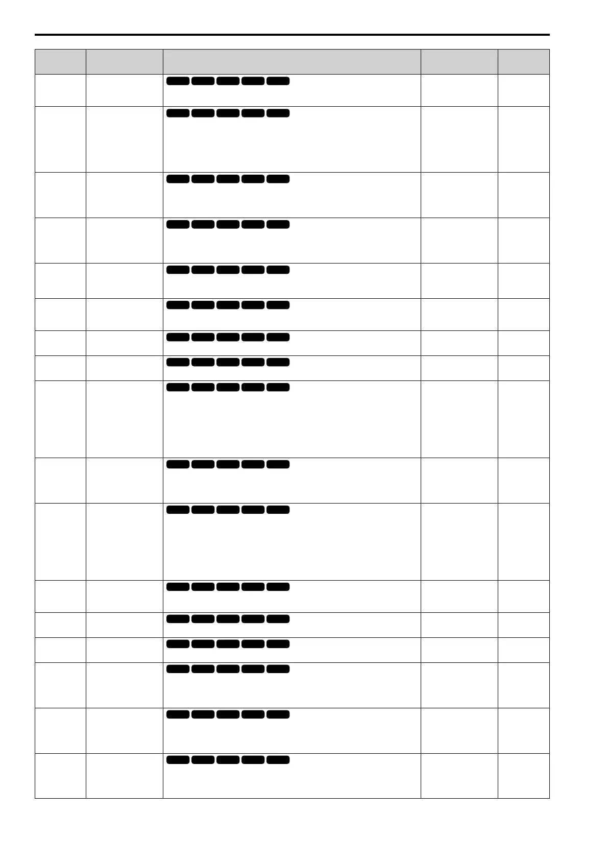
No.
(Hex.)
Name Description
Default
(Range)
Ref.
b5-38
(01FE)
PID SP User Scale for
Display
Sets the value that the drive sets or shows as the PID setpoint when at the maximum
output frequency.
Determined by b5-20
(1 - 60000)
477
b5-39
(01FF)
PID SP User digits for
Display
Sets the number of digits to set and show the PID setpoint.
0 : No Decimal Places
1 : 1 Decimal Place
2 : 2 decimal places
3 : 3 Decimal Places
Determined by b5-20
(0 - 3)
477
b5-40
(017F)
Fref Mon@PID
Sets the contents for monitor U1-01 [Frequency Reference] in PID control.
0 : U1-01 with PID Output
1 : U1-01 without PID Output
0
(0, 1)
478
b5-47
(017D)
PID Out Rev Operation
Mode
Sets reverse motor rotation when the PID control output is negative.
0 : Lower Limit is Zero
1 : Negative Output Accepted
1
(0, 1)
478
b5-53
(0B8F)
RUN
PID I Ramp Limit
Sets the responsiveness of PID control when the PID feedback changes quickly.
0.0 Hz
(0.0 - 10.0 Hz)
478
b5-55
(0BE1)
PID Fback Mon
Selection
Sets the monitor (Ux-xx) used as the PID Feedback. Set the x-xx part of the Ux-xx
[Monitor].
000
(000 - 999)
479
b5-56
(0BE2)
PID FdbkMon Gain
Sets the gain for the monitor set in b5-55 [PID Fback Mon Selection].
1.00
(0.00 - 10.00)
479
b5-57
(11DD)
PID FdbkMon Bias
Sets the bias for the monitor specified in b5-55 [PID Fback Mon Selection].
0.00
(-10.00 - +10.00)
479
b5-58 to b5-60:
(1182 - 1184)
RUN
PID Setpoints 2 to 4
Sets the PID setpoint when H1-xx = 77 or 78 [MFDI Function Selection = PID SP 1,
PID SP 2]. This value is a percentage of the maximum output frequency.
Note:
Parameter A1-02 [Control Method] selects which parameter is the maximum output
frequency.
• A1-02 ≠ 8 [EZ Vector]: E1-04 [Max Output Frequency]
• A1-02 = 8: E9-02 [Maximum Speed]
0.00%
(0.00 - 100.00%)
479
b5-61
(119A)
PID LoLim Select for
Trim Mode
Sets the function that adjusts the PID output in relation to the frequency reference.
0 : Disabled
1 : Enabled
0
(0, 1)
479
b5-62
(119B)
PID LoLim Value for
Trim Mode
Sets the PID Trim Mode Lower Limit Value as a percentage of the maximum output
frequency.
Note:
Parameter A1-02 [Control Method] selects which parameter is the maximum output
frequency.
• A1-02 ≠ 8 [EZ Vector]: E1-04 [Max Output Frequency]
• A1-02 = 8: E9-02 [Maximum Speed]
0.00%
(0.00 - 100.00%)
480
b5-63
(119C)
PID DifFB Mon
Selection
Selects the monitor (Ux-xx) used as the PID Differential Feedback. Set the x-xx part of
the Ux-xx [Monitor].
000
(000 - 999)
480
b5-64
(119D)
PID DifFB Mon Gain
Sets the gain for the monitor specified in b5-63 [PID DifFB Mon Selection].
1.00
(0.00 - 10.00)
480
b5-65
(119F)
PID DifFB Mon Bias
Sets the bias for the monitor specified in b5-63 [PID DifFB Mon Selection].
0.00
(-10.00 - +10.00)
480
b5-66
(11DE)
PID Fback Mon Level
Sets the signal level for the monitor specified in b5-55 [PID Fback Mon Selection].
0 : Absolute
1 : Bi-directional (+/-)
0
(0, 1)
480
b5-67
(11DF)
PID DifFB Mon Level
Sets the signal level for the monitor specified in b5-63 [PID DifFB Mon Selection].
0 : Absolute
1 : Bi-directional (+/-)
0
(0, 1)
480
b5-89
(0B89)
RUN
Sleep Method Selection
Sets sleep and wake up operation when using PID.
0 : Standard
1 : EZ Sleep/Wake-up
0
(0, 1)
481

 Loading...


