Main module - motherboard
Overview of modules
A31003-K16-X001-3-7620
,
07/99
3-10
Hicom 100 E Version 2.1, Service manual
3.4 Main module - motherboard
The MB 6/4 motherboard is the main board and accommodates 6 digital extension interfaces
(U
P0/E
), 4 analogue extension interfaces (a/b), the V.24 interface (SIC – serial interface cable),
an integrated digital modem, the signalling unit (SIU), a real-time clock with NC battery, and a
PCM highway controller and conference circuit.
Hicom 108 MB 2/4 - motherboard with 2 x U
P0/E
, 4 x a/b (see Table 3-9)
Hicom 112 MB 4/4 - motherboard with 4 x U
P0/E
, 4 x a/b (see Table 3-10)
Hicom 118 MB 6/4 - motherboard with 6 x U
P0/E
, 4 x a/b (see Table 3-11)
An EXM or MPPI module can be connected to the MB for external music on hold. The module
also has a V.24 interface with a mini-DIN connector that can be used for outputting or editing
call charge data or customer data. Teleservice is possible via both the V.24 interface and the
digital modem (in connection with a digital trunk of the STLS module).
U
P0/E
/ a/b extensions are connected by means of screw terminals. These terminals can be re-
moved from the module for installation or maintenance purposes.
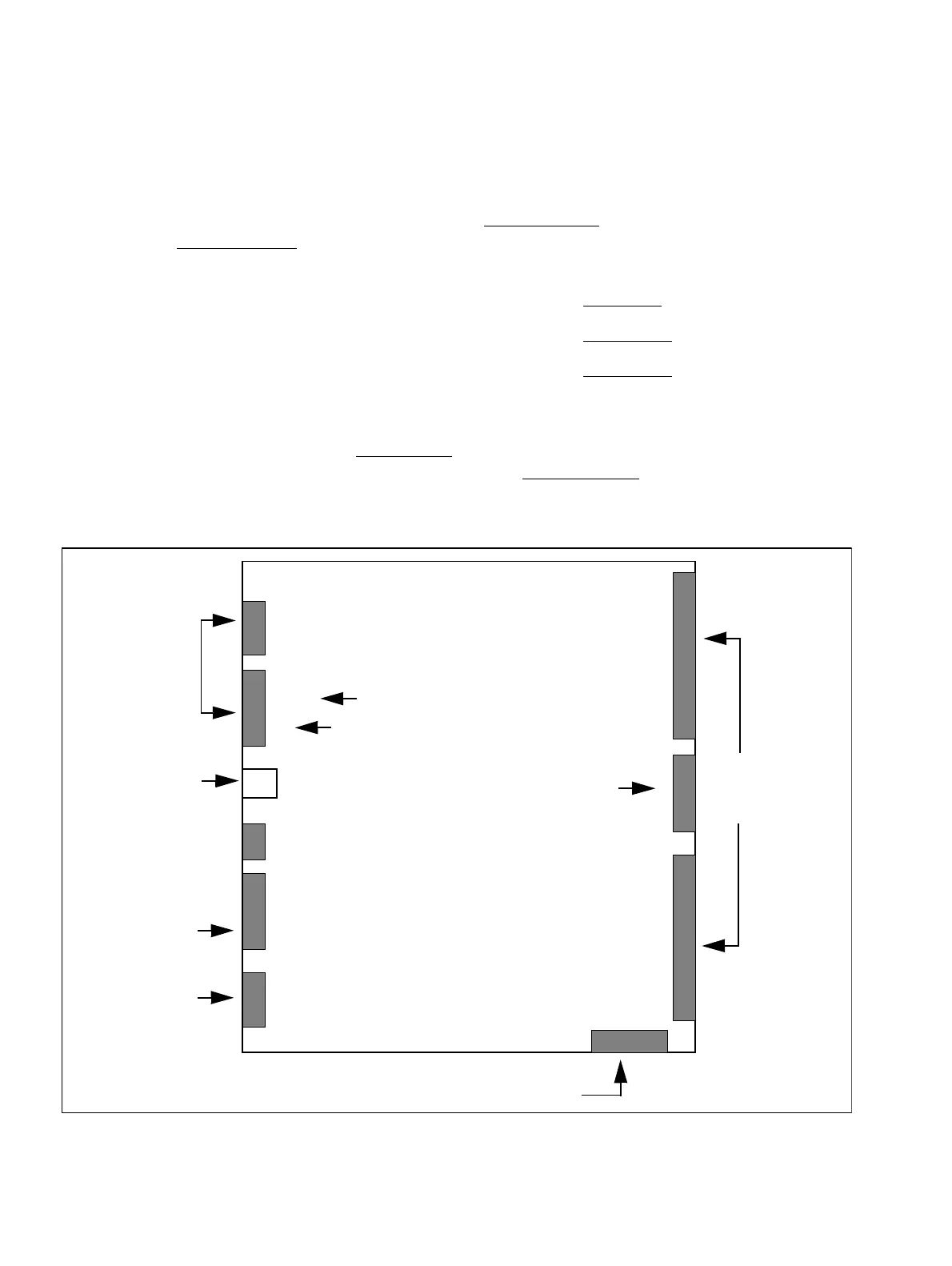
Figure 3-3 Motherboard interfaces (SW 2.0.1+)
X1
X2
SIC
X3
X4
Options bus
MB
U
P0/E
ports
1...6
X10
a/b ports
1...4
EXM / MPPI
3 and 4
1 and 2
PSU/UPS
1
8
1
4
5
12
1
10
V.24 adapter
Not assigned for MB2/4
X11
MDF side
PSU/UPS side
GND
Plug connector as
of SW 2.0.2
System
expansion
9 -12 not assigned
for MB4/4
 Loading...