Installing cards for system expansions
Installation
A31003-K16-X001-3-7620
,
07/99
5-6
Hicom 100 E Version 2.1, Service manual
5.4 Installing cards for system expansions
The new equipping sequence must be observed when installing subsequent expansions to the
Hicom 118. This is the counting scheme for the individual slots:
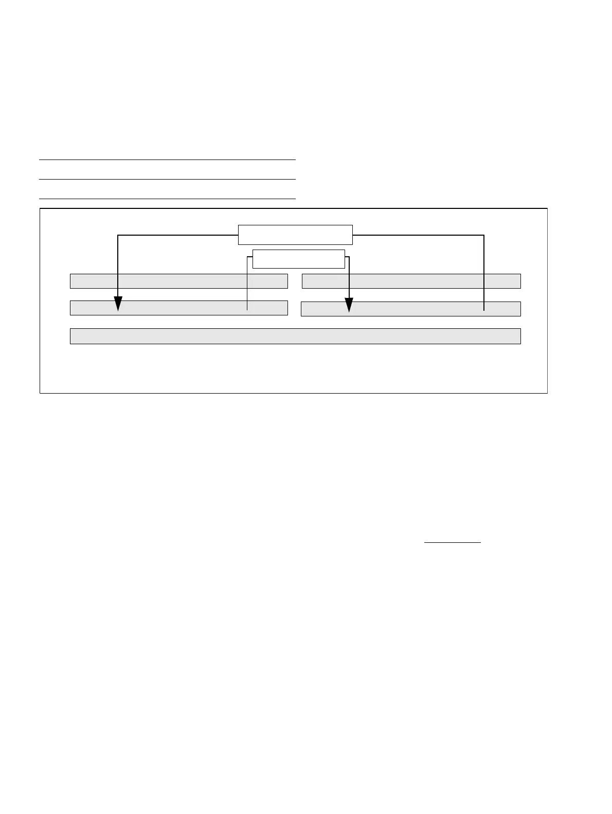
Figure 5-4 Equipping sequence for subscriber and trunk modules
Connect system expansions to one another and to the MB via ribbon cable, noting ribbon cable
colour coding.
5.4.1 Installing or replacing an SLU8
After the power supply has been disconnected, at least 2 min. must elapse before the SLU can
be removed or a new SLU module can be plugged.
Failure to adhere to this requirement could result in damage to the MB Figure 3-7.
5.5 Extension and line number allocation
The extension and line numbers are allocated consecutively during system startup.
The following rules apply to consecutive extension number allocation:
●
The system configuration status is stored in the EEPROM on first initialisation. This data is
accessed after each system reset and the system’s extension number play is generated
from this data.
●
If a changed equipping scheme is detected during startup:
– Missing or defective module > no action.
Trunk modules 1 2 4 3
Subscriber modules 3 4 2 1
MB
Slot 1
Slot 2
Slot 3
Slot 4
Trunk modules
Subscriber modules
View from the PSU side
 Loading...