A31003-K16-X001-3-7620, 07/99
Hicom 100 E Version 2.1, Service manual
5-1
Selecting the most suitable locatio
Installation
5 Installation
Hicom 108/112/118 are compact, digital, Euro-ISDN-compatible telephone systems belonging
to the Hicom 100 E product family. They may consist of several components depending on the
version and on the requirements. These instructions are intended for
Siemens field engineers
or the
specialist contractors
, who install, connect and commission the individual components
of the Hicom 108/112/118 system.
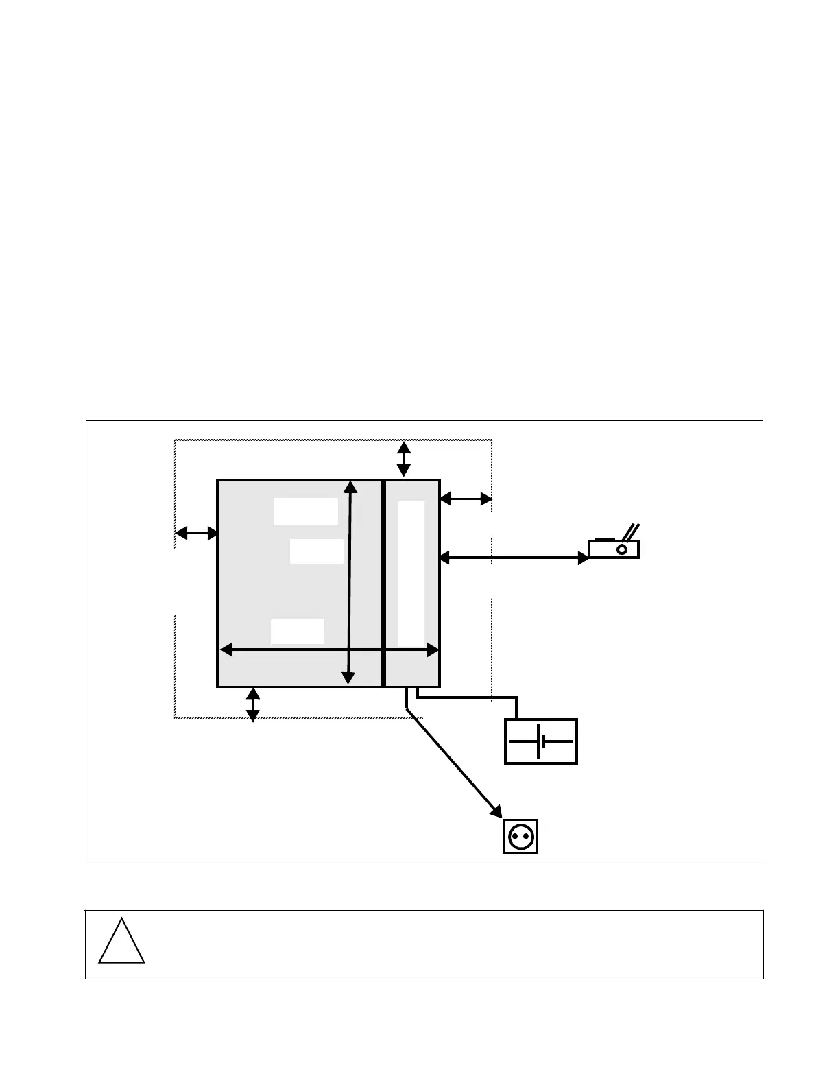
5.1 Selecting the most suitable location
●
Note the dimensions of and clearances required by the system and an expansion box
●
A mains socket must be within convenient reach
●
Do not install near sources of heat or electrical fields.
Figure 5-1 Location, dimensions and minimum clearances
Caution
The systems are only suitable for wall mounting.
max. 40 cm
Battery box
max. 300 cm
Socket
(230 V
∼
)
Printer
min. 10 cm
for opening
the MDF
150 cm
min. 30 cm
P
S
U
U
P
S
37 cm
47 cm
Unit
20 cm
min. 10 cm for
each expansion
(basic box only)
30 cm
Basic box and
expansion box
!
 Loading...