Function expansions with options bu
A31003-K16-X001-3-7620, 07/99
Hicom 100 E Version 2.1, Service manual
3-21
Overview of modules
3.6 Function expansions with options bus
Function expansions can be connected to the O-bus (options bus) interface as required. No
major hardware adaptations are necessary. The central processor recognises the connected
modules when the system is booted and supplies them with the requisite parameters for initial-
isation. All modules are of the plug-in type. Up to four of a given module can be inserted (ex-
ception: only one STRB), or different modules can be combined as required.
3.6.1 Options adapter
The options bus adapter (OPA) is a mechanical and electrical adapter between the first options
module and the system motherboard.
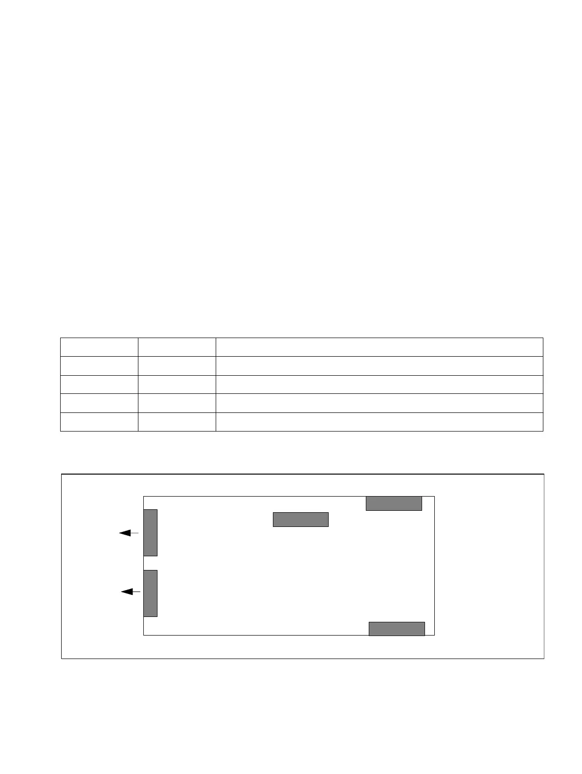
3.6.2 GEE module
There are 4 call metering receivers in each of the modules listed below. These receivers regis-
ter the call charge pulses and perform initial processing functions:
●
The channel for call charge recognition is looped into the trunk and then routed to the TLA.
.
Figure 3-12 GEE module, interfaces
Module Frequency Configurable for
GEE 12 12kHz ITL, POR, SWZ, SPA, IM, FRA, AUS
GEE 16 16kHz BEL, GER without blocking circuit
GEE 16 16kHz FIN, RSA with blocking circuit
GEE 50 50Hz NDL, GBR
Table 3-18 GEE module, national versions
GEE module
MB side
Module side
X1
X4
1
10
X3
1
8
to TLA
X5
1
10
to trunk
MSI
X2
 Loading...