PLC device configuration
6.1 Configuring the operation of the PLC system
S7-200 SMART
System Manual, 09/2015, A5E03822230-AC
121
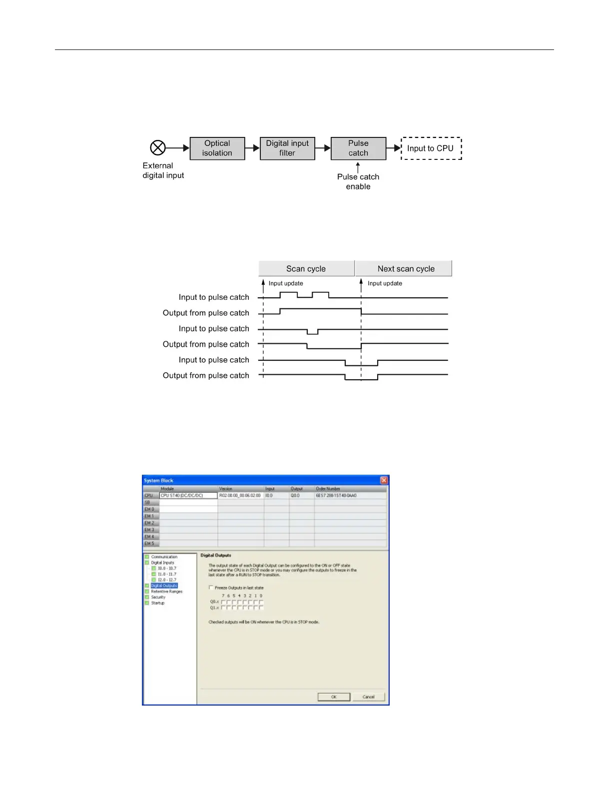
Because the pulse catch function operates on the input after it passes through the input filter,
you must adjust the input filter time so that the pulse is not removed by the filter. The figure
below shows a block diagram of the digital input circuit:
The figure below shows the response of an enabled pulse catch function to various input
conditions. If you have more than one pulse in a given scan, only the first pulse is read. If
you have multiple pulses in a given scan, you should use the rising/falling edge interrupt
events:
Configuring the digital outputs
Click the Digital Outputs node of the system block (Page 115) to configure options for the
digital outputs of the selected module.

 Loading...


