Communication
8.5 PROFIBUS
S7-200 SMART
382 System Manual, 09/2015, A5E03822230-AC
Note
In the examples above, the CPU 315
-2 DP is the configured DP master. Depending on the
master CPU type, the EM DP01 "Properties" can appear slightly different than those shown
here.
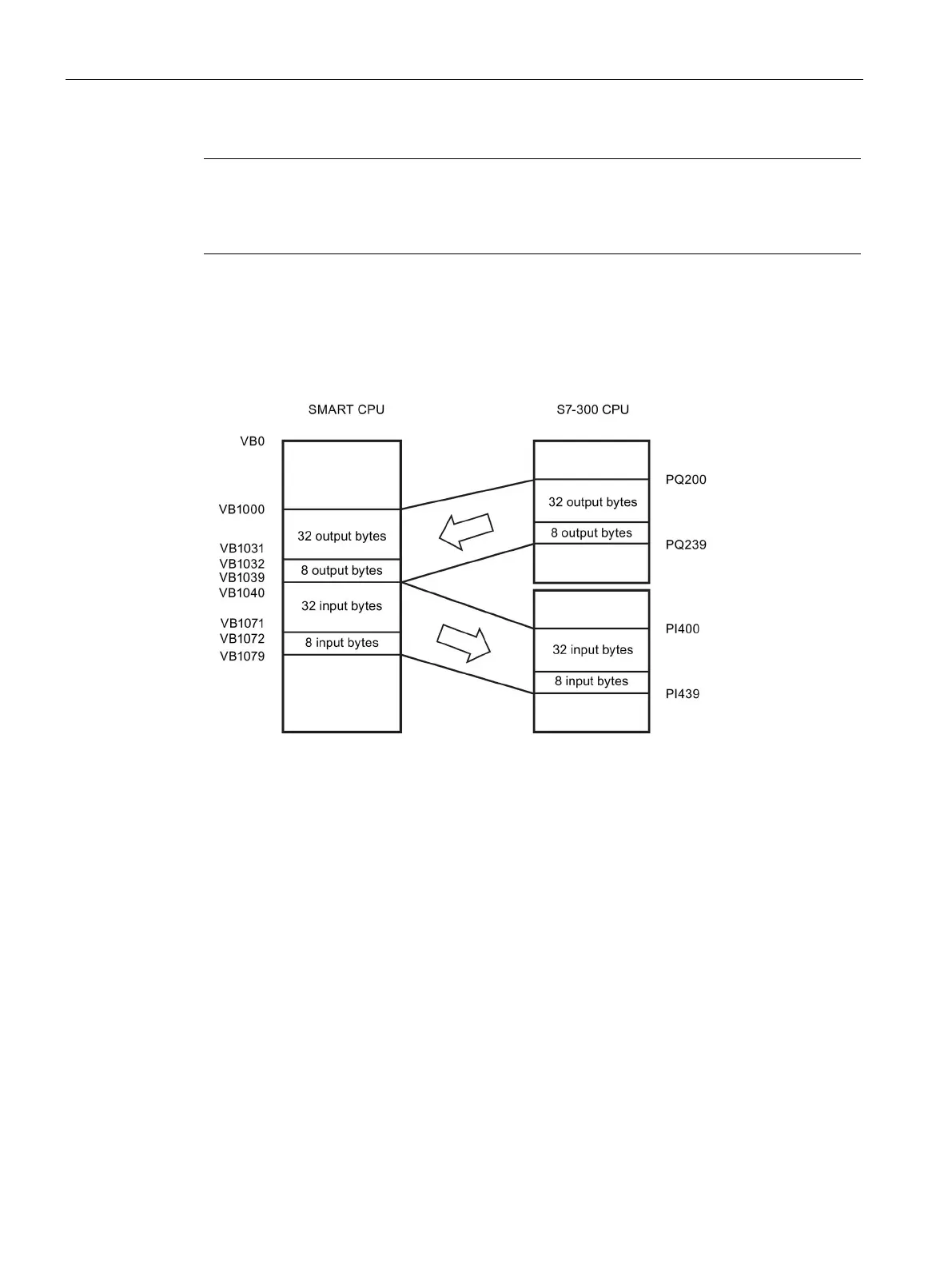
Example of V memory and I/O address area
The following figure shows an example of the V memory in the S7-200 SMART CPU and the
I/O address area of an S7-300 PROFIBUS DP master:
In this example, the DP master has defined an I/O configuration consisting of two slots and a
V memory offset of 1000. The example configures the first slot as 32 bytes in and out and
the second slot as 8 bytes in and out. The output and input buffers in the S7-200 SMART
CPU are both 40 bytes (32 + 8). The output data (from the DP master) buffer starts at
V1000; the input data (to the DP master) buffer immediately follows the output buffer and
begins at V1040.
 Loading...


