PLC device configuration
6.1 Configuring the operation of the PLC system
S7-200 SMART
122 System Manual, 09/2015, A5E03822230-AC
You can set digital output points to a specific value when the CPU is in STOP mode, or
preserve the output states that existed before the transition to STOP mode.
You have two ways to set the digital output behavior in STOP mode:
●
Freeze Outputs in last state:
Click this checkbox to have all digital outputs frozen in their
last states at the time of a RUN-to-STOP transition.
●
If the Freeze Outputs in last state checkbox is not checked, this table
allows you to select the desired state of each output whenever the CPU is in STOP
mode. Click the checkbox for each output you want set to ON (1). The default substitute
value for digital outputs is OFF (0).
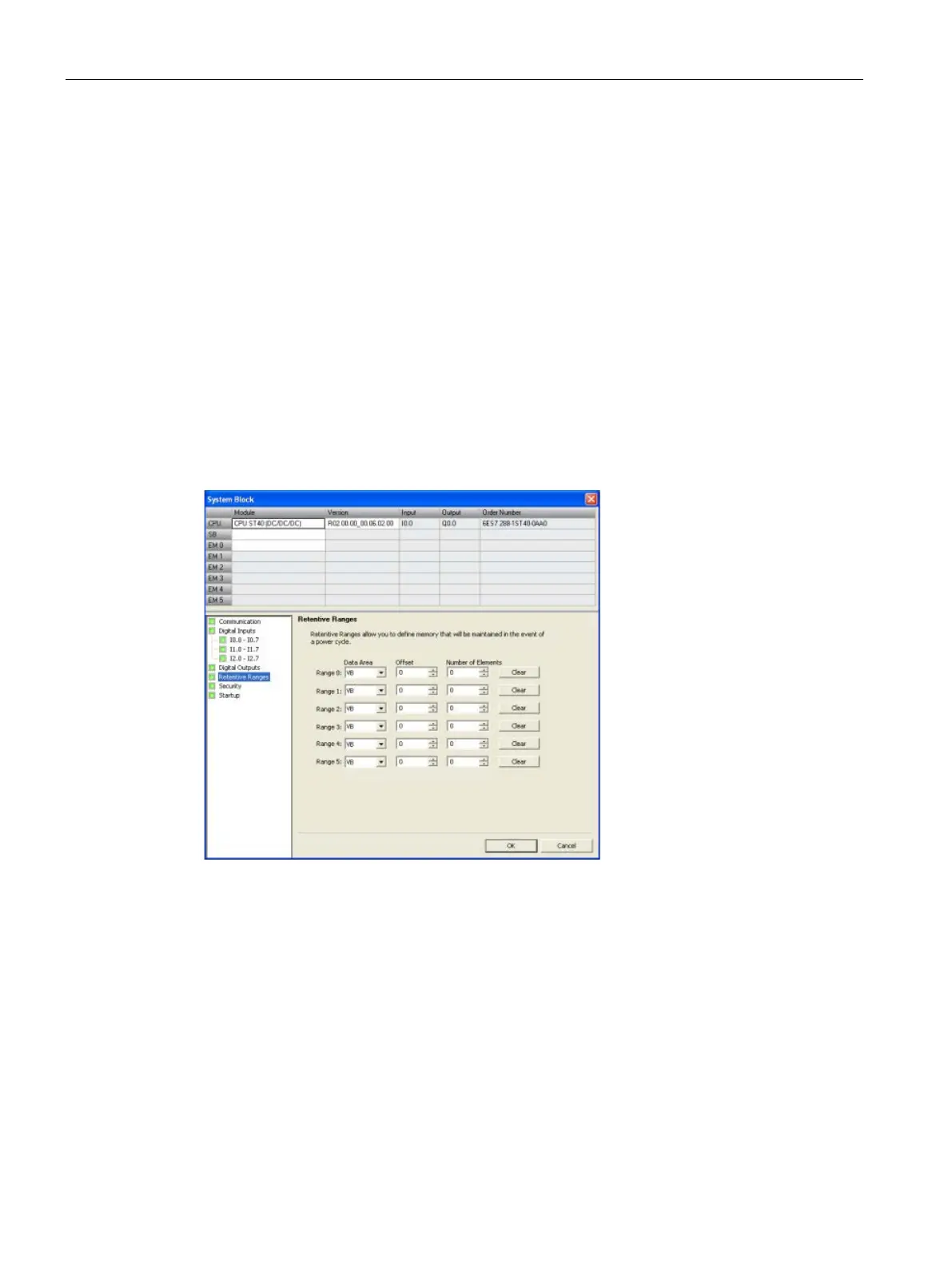
Configuring the retentive ranges
Click the Retentive Ranges node of the system block (Page 115) dialog to configure ranges
of memory that will be retained following a power cycle.
Configure the areas of memory you want to retain through power cycles. Enter new values
for V, M, T, or C memory.
You can define ranges of addresses in the following memory areas to be retentive: V, M, T,
and C. For timers, only the retentive timers (TONR) can be retained, and, for both timers and
counters, only the current value can be retained (timer and counter bits are cleared on each
power-up).
By default, no retentive areas are defined in the CPU, but you can configure the retentive
ranges so that up to 10 Kbytes of memory are retentive.
 Loading...


