EasyManuals Logo

Siemens Simatic S7 Series System Manual

Siemens Simatic S7 Series
726 pages
To Next Page IconTo Next Page
To Previous Page IconTo Previous Page
Page #650 background imageLoading...
Page #650 background image
Technical specifications
A.10 EM DP01 PROFIBUS DP module
S7-200 SMART
650 System Manual, 09/2015, A5E03822230-AC
A.10.2
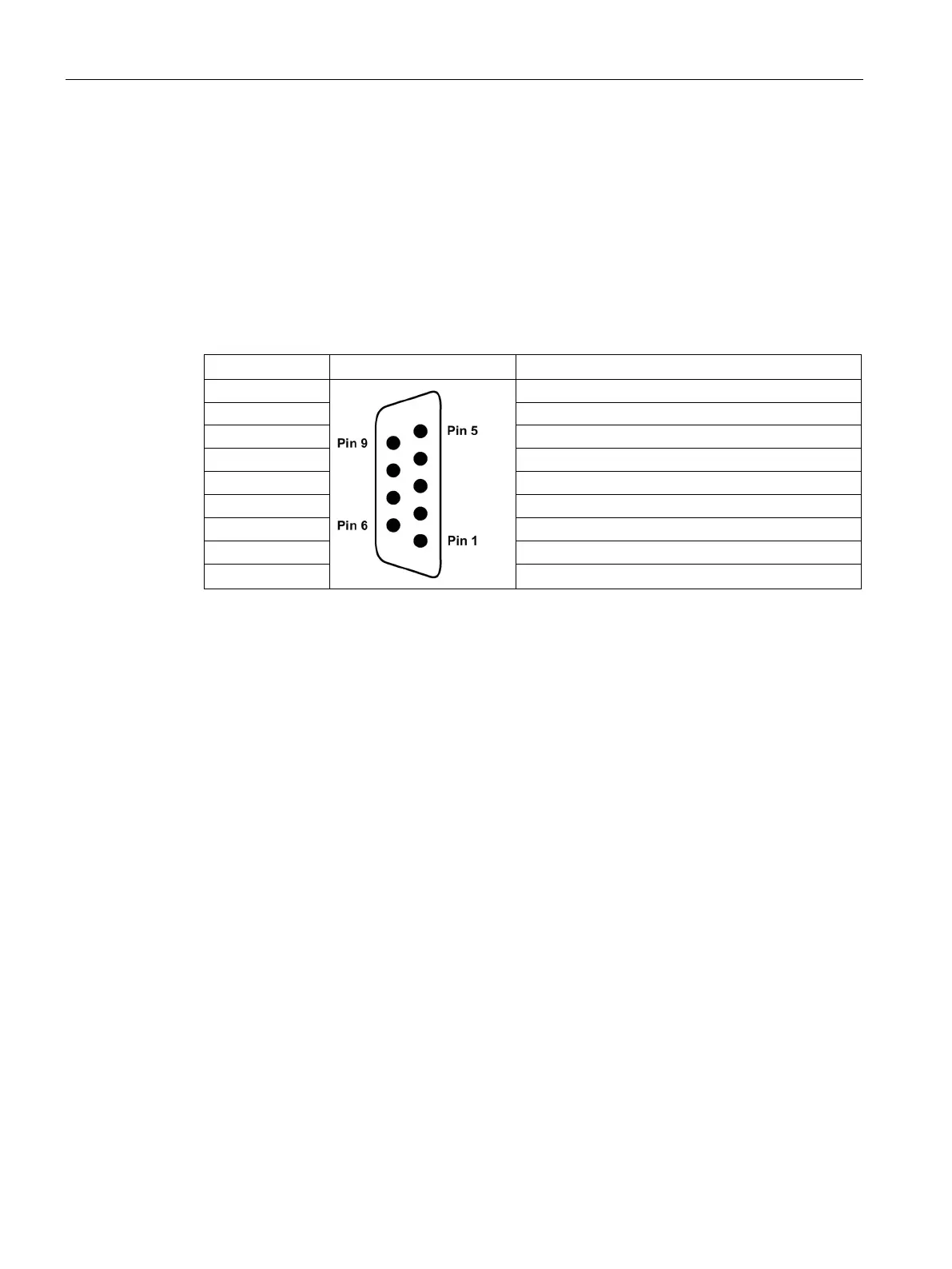
Connector pin assignments for EM DP01
The RS485 communication serial port on the EM DP01 is RS485-compatible on a nine-pin
subminiature D female connector, in accordance with the PROFIBUS standard as defined in
the European Standard EN 50170. The following table shows the connector that provides
physical connection for the communication port and describes the communication port pin
assignments.
Table A- 151 Pin assignments for the S7-200 SMART EM DP01
Pin Number
Connector
PROFIBUS
1
Shield
2 24 V Return
3
RS485 Signal B
4 Request-to-Send
5
5 V Return
6
+5 V (isolated)
7
+24 V
8
RS485 Signal A
9 NC

Table of Contents

Other manuals for Siemens Simatic S7 Series

Questions and Answers:

Question and Answer IconNeed help?

Do you have a question about the Siemens Simatic S7 Series and is the answer not in the manual?

Siemens Simatic S7 Series Specifications

General IconGeneral
CPUVaries by model (e.g., S7-300, S7-400, S7-1200, S7-1500)
Communication InterfacesPROFIBUS, PROFINET, Ethernet, MPI
ProgrammingTIA Portal, STEP 7
Programming LanguagesLAD, FBD, STL, SCL, GRAPH
I/O ModulesDigital, Analog, Specialty modules available
Operating Temperature0°C to 60°C (standard models)
MountingDIN rail mounting
Operating Voltage24V DC or 120/230V AC (varies by model)
Protection ClassIP20 (standard models)
MemoryVaries depending on the S7 model. Includes work memory (RAM) for program execution, load memory (EEPROM or Flash) for program storage, and system memory for operating system functions. Memory sizes range from kilobytes to megabytes.

Related product manuals