Getting started
2.2 Creating the sample program
S7-200 SMART
32 System Manual, 09/2015, A5E03822230-AC
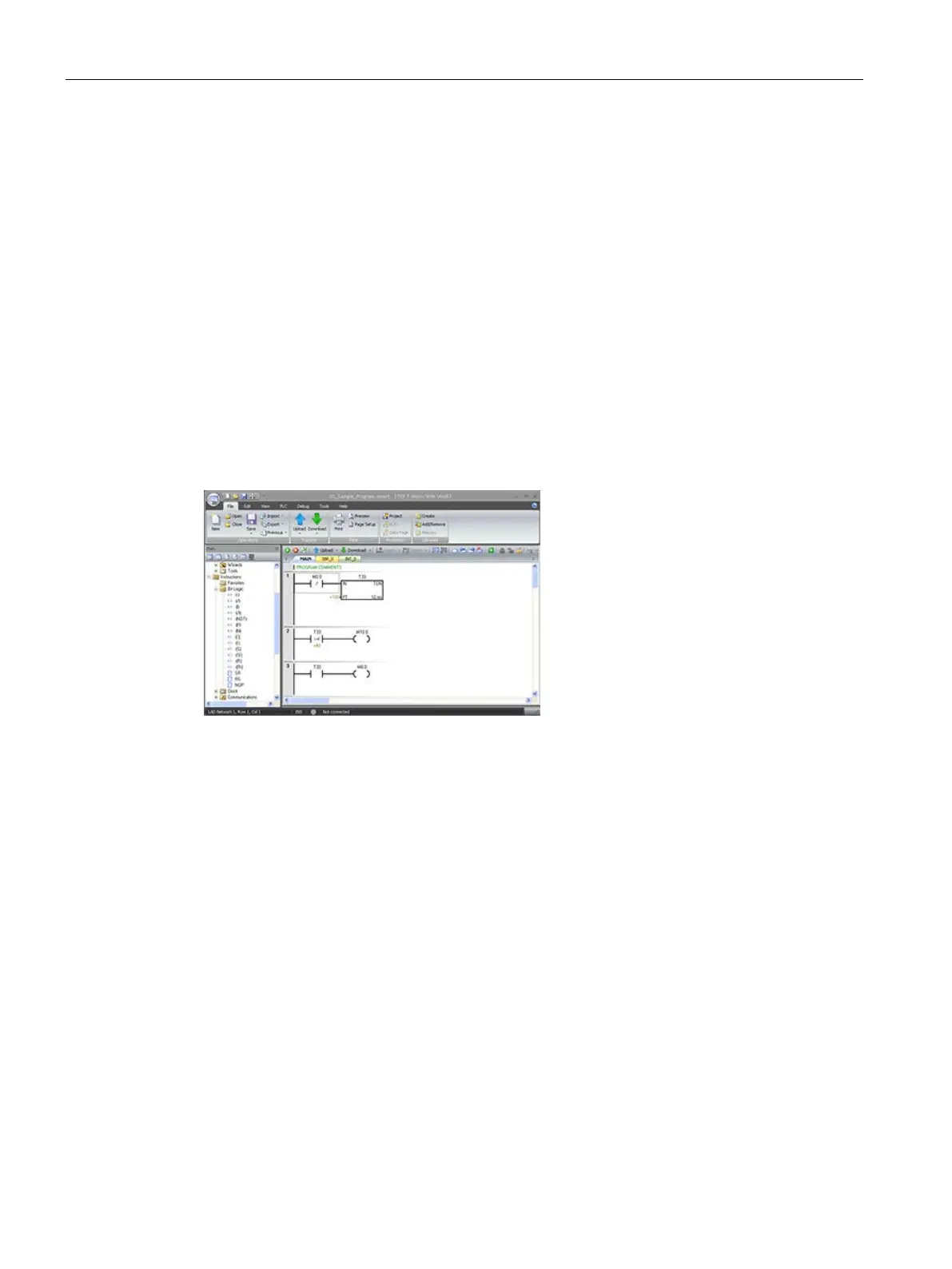
To enter the instruction for turning on output M10.0:
1. Double-click the Bit Logic icon to display the bit logic instructions and select the output
coil.
2. Hold down the left mouse button and drag the coil onto the second network.
3. Click "???" above the coil and enter the following address: M10.0
4. Press the Return key to enter the address for the coil.
Network 3: Resetting the timer
Network 3: Resetting the timer
When the timer reaches the pre
set
value (100) and turns the timer bit on,
the contact for T33 turns on. Power
flow from this contact turns on the
M0.0 memory location. Because the
timer is enabled by a Normally Closed
contact for M0.0, changing the state of
M0.0 from off (0) to on (1)
resets the
To enter the contact for the timer bit of T33:
1. Select the "Normally Open" contact from the bit logic instructions.
2. Hold down the left mouse button and drag the contact onto the third network.
3. Click "???" above the contact and enter the address of the timer bit: T33
4. Press the Return key to enter the address for the contact.
To enter the coil for turning on M0.0:
1. Select the output coil from the bit logic instructions.
2. Hold down the left mouse button and drag the output coil onto the third network.
3. Click "???" above the coil and enter the following address: M0.0
4. Press the Return key to enter the address for the coil.

 Loading...


