PID loops and tuning
11.1 PID loop definition table
S7-200 SMART
468 System Manual, 09/2015, A5E03822230-AC
PID loop definition table
Eighty (80) bytes are allocated for the loop table from the starting address you enter for
Table (TBL) in the PID instruction box. The PID instruction for the S7-200 SMART CPU
references this loop table that contains the loop parameters.
If you use the PID Tune control panel, all interaction with the PID loop table is handled for
you by the control panel. If you need to provide auto-tuning capability from an operator
panel, your program must provide the interaction between the operator and the PID loop
table to initiate and monitor the auto-tuning process, and then apply the suggested tuning
values.
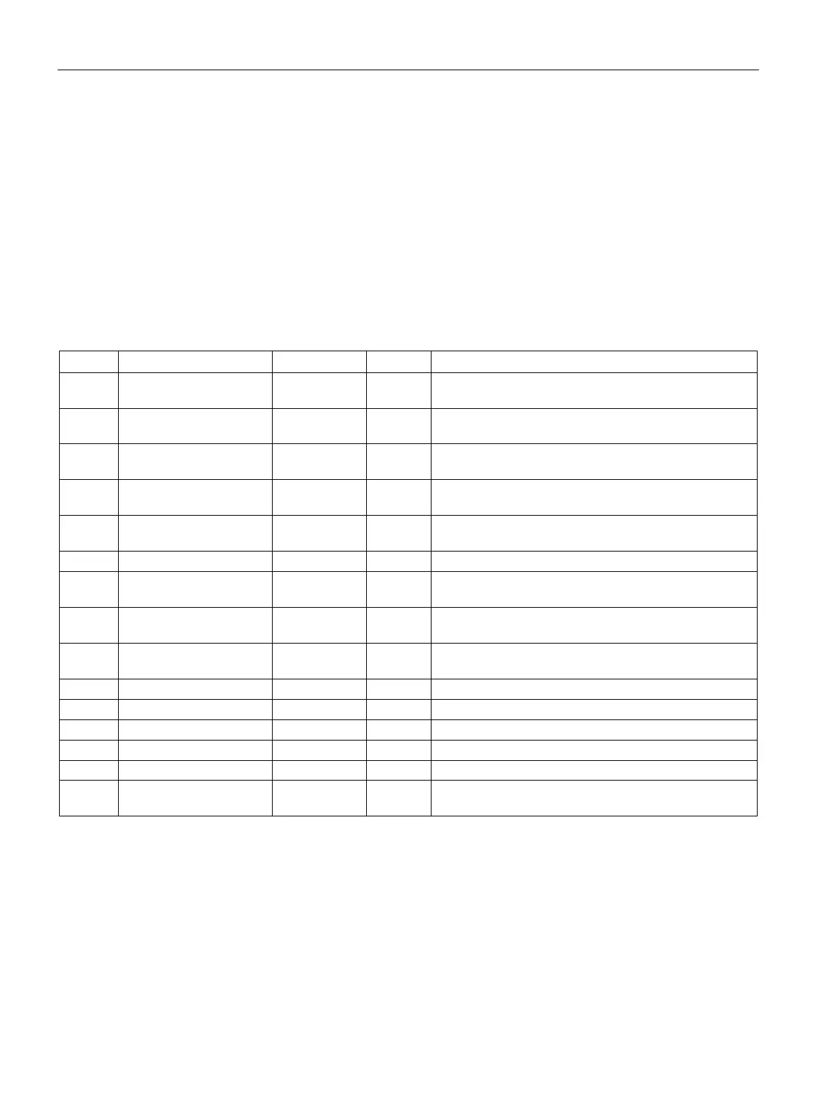
Table 11- 1 Loop table
0 Process variable (PV
n
) REAL In Contains the process variable, which must be scaled
4 Setpoint (SP
n
) REAL In Contains the setpoint, which must be scaled between
0.0 and 1.0.
8 Output (M
n
) REAL In/Out Contains the calculated output, scaled between 0.0 and
12 Gain (K
C
) REAL In Contains the gain, which is a proportional constant. Can
be a positive or negative number.
16 Sample time (T
S
) REAL In Contains the sample time, in seconds. Must be a posi-
Integral time or reset (T
I
)
Contains the integral time or reset, in minutes.
24 Derivative time or rate
D
REAL In Contains the derivative time or rate, in minutes.
28 Bias (MX) REAL In/Out Contains the bias or integral sum value between 0.0 and
32 Previous process varia-
n-1
REAL In/Out Contains the value of the process variable stored from
the last execution of the PID instruction.
'PIDA' (PID Extended Table, Version A): ASCII constant
44 Deviation (DEV) REAL In Normalized value of the maximum PV oscillation ampli-
tude (range: 0.025 to 0.25).

 Loading...


