Getting started
2.1 Connecting to the CPU
S7-200 SMART
System Manual, 09/2015, A5E03822230-AC
27
Establishing the hardware communication connection
The Ethernet interfaces establish the physical connections between a programming device
and a CPU. Since Auto-Cross-Over functionality is built into the CPU, either a standard or
crossover Ethernet cable can be used for the interface. An Ethernet switch is not required to
connect a programming device directly to a CPU.
Follow the steps below to create the hardware connection between a programming device
and a CPU:
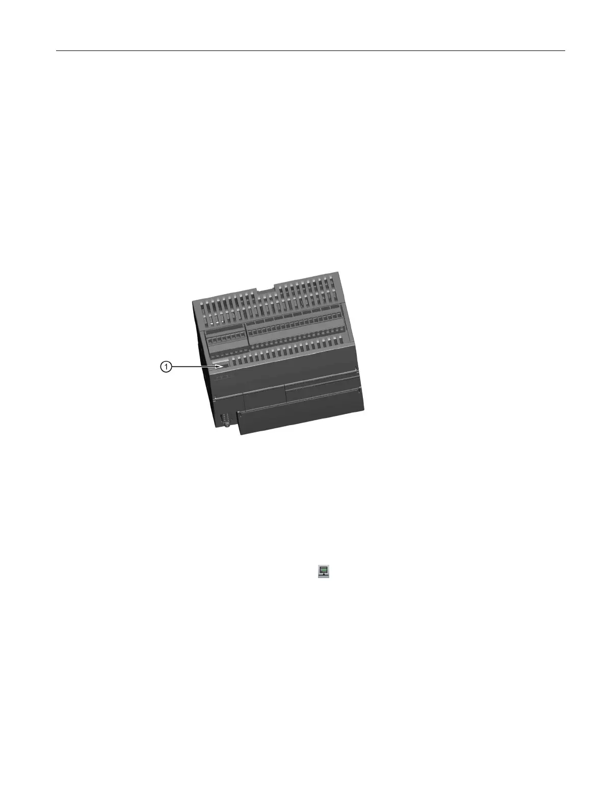
1. Install the CPU.
2. Remove the RJ45 connection cover from the Ethernet port. Retain the cover for reuse.
3. Plug the Ethernet cable into the Ethernet port on top of the CPU as shown below.
4. Connect the Ethernet cable to the programming device.
Setting up communication with the CPU
From STEP 7-Micro/WIN SMART, use one of the following methods to display the
"Communications" dialog for configuring communication to the CPU.
● From the project tree, double-click the "Communications" node.
● Click the "Communications" button
from the navigation bar.
● Select "Communications" from the Component drop-down list in the Windows area of the
View menu ribbon strip.
The "Communication" dialog provides two methods of selecting the CPU to be accessed:
● Click the "Find CPUs" button to have STEP 7-Micro/WIN SMART search your local
network for CPUs. The IP address of each CPU found on the network is listed under
"Found CPUs".
● Click the "Add CPU ..." button to manually enter the access information (IP address and
so forth) for a CPU that you wish to access. The IP address for each CPU, manually
added with this method, is listed under "Added CPUs" and is retained.

 Loading...


