Program instructions
7.1 Bit logic
S7-200 SMART
156 System Manual, 09/2015, A5E03822230-AC
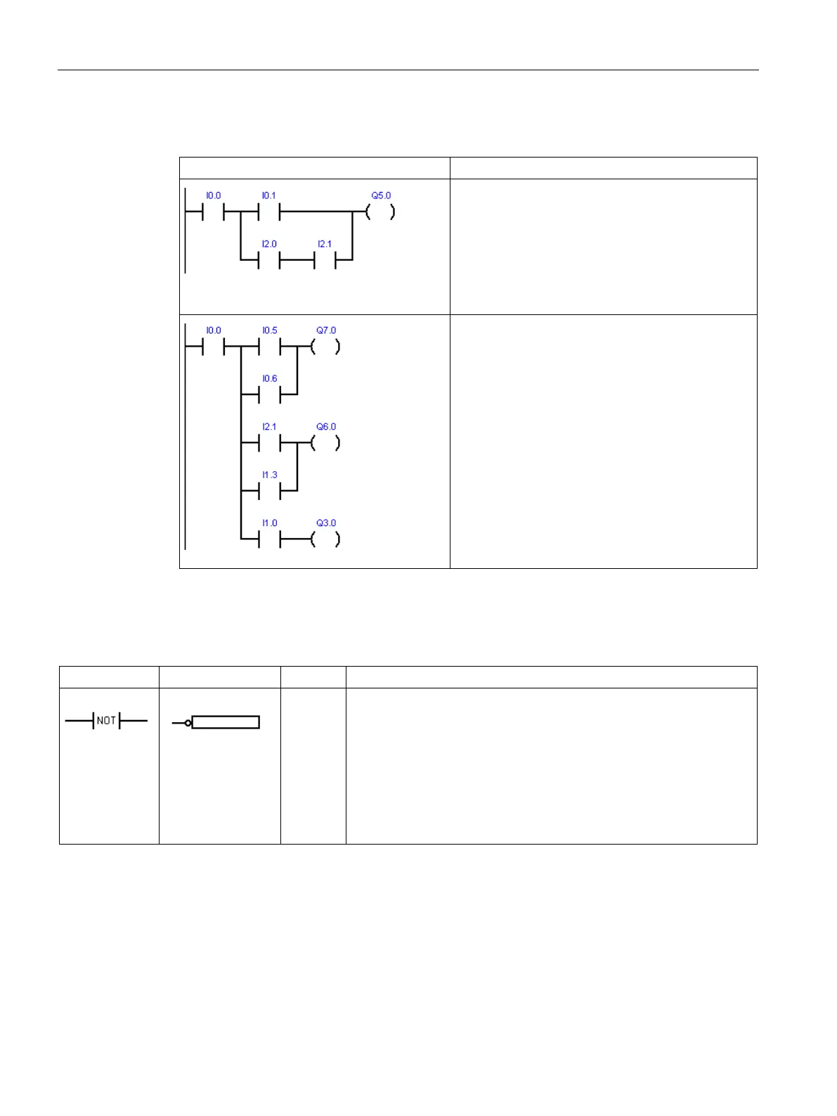
Logic Stack example: LAD networks transformed into STL code
LD I0.0
LD I0.1
LD I2.0
A I2.1
OLD
ALD
LD I0.0
LPS
LD I0.5
O I0.6
ALD
= Q7.0
LRD
LD I2.1
O I1.3
ALD
= Q6.0
LPP
A I1.0
The Not instruction (NOT) inverts the state of the power flow input.
: The NOT contact changes the state of power flow input. When
power flow reaches the NOT contact, it stops. When power flow does
not reach the NOT contact, it supplies power flow.
: The NOT instruction is represented as a graphical negation (bub-
ble) symbol on Boolean box input connectors and functions as a logic
state inverter.
: The NOT instruction changes the value on the top of the stack
from 0 to 1, or from 1 to 0.
Bit logic input examples (Page 162)

 Loading...


