Communication
8.4 Ethernet
S7-200 SMART
System Manual, 09/2015, A5E03822230-AC
371
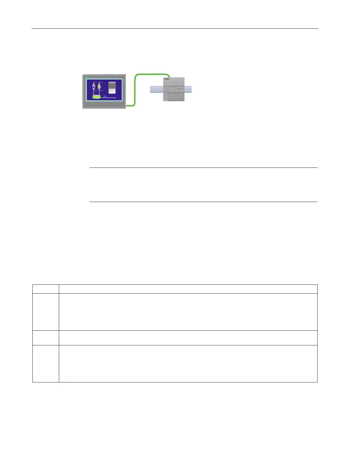
The CPU supports Ethernet communication
connections to HMIs. The following requir
e-
st be considered when setting up
communications between CPUs and HMIs:
Configuration/Setup:
● The CPU must be configured with an IP address.
● The HMI must be setup and configured to connect with the IP address of the CPU.
● No Ethernet switch is required for one-to-one communications; an Ethernet switch is
required for more than two devices in a network.
-mounted CSM1277 4-port Ethernet switch can be used to connect your CPUs
and HMI devices. The Ethernet port on the CPU does not contain an Ethernet switching
device.
Supported functions:
● The HMI can read/write data to the CPU.
● Messages can be triggered, based upon information retrieved from the CPU.
● System diagnostics
To ensure that your CPU and HMI are communicating properly, follow the sequence of steps
in the table below:
Table 8- 1 Required steps in configuring communications between an HMI and a CPU
1 Establishing the hardware communications connection
An Ethernet interface establishes the physical connection between an HMI and a CPU. Since Auto-Cross-Over
functionality is built into the CPU, you can use either a standard or crossover Ethernet cable for the interface.
An Ethernet switch is not required to connect an HMI and a CPU.
Refer to "Establishing the hardware communications connection" (Page 27) for more information.
2 If you have already created a project with a CPU, open your project in STEP 7-Micro/WIN SMART. If not, cre-
ate a project and insert a CPU In the project.
3 Configuring an IP address in your project
Use the same configuration process; however, you must configure IP addresses for the HMI and the CPU. You
must download the configuration for each CPU and HMI device.
Refer to "Configuring or changing an IP address for a CPU or device in your project" (Page 362) for more in-
formation.

 Loading...


