PID loops and tuning
11.4 Auto-tune sequence
S7-200 SMART
System Manual, 09/2015, A5E03822230-AC
473
The deviation parameter specifies the desired peak-to-peak swing of the PV around the
setpoint. If you select to automatically determine this value, the desired deviation of the PV is
computed by multiplying the hysteresis value by 4.5. The output will be driven proportionally
to induce this magnitude of oscillation in the process during auto-tuning.
The auto-tuning sequence begins after the hysteresis and deviation values have been
determined. The tuning process begins when the initial output step is applied to the loop
output.
This change in output value causes a corresponding change in the value of the process
variable. When the output change drives the PV away from setpoint far enough to exceed
the hysteresis boundary, a zero-crossing event is detected by the auto-tuner. Upon each
zero-crossing event, the auto-tuner drives the output in the opposite direction.
The tuner continues to sample the PV and waits for the next zero-crossing event. The tuner
requires a total of twelve zero-crossings to complete the sequence. The magnitude of the
observed peak-to-peak PV values (peak error) and the rate at which zero-crossings occur
are directly related to the dynamics of the process.
Early in the auto-tuning process, the output step value is proportionally adjusted once to
induce subsequent peak-to-peak swings of the PV to more closely match the desired
deviation amount. Once the adjustment is made, the new output step amount is written into
the Actual Step Size field (ASTEP) of the loop table.
If the time between zero-crossings exceeds the zero-crossing watchdog interval time, the
auto-tuning sequence is terminated with an error. The default value for the zero-crossing
watchdog interval time is two hours.
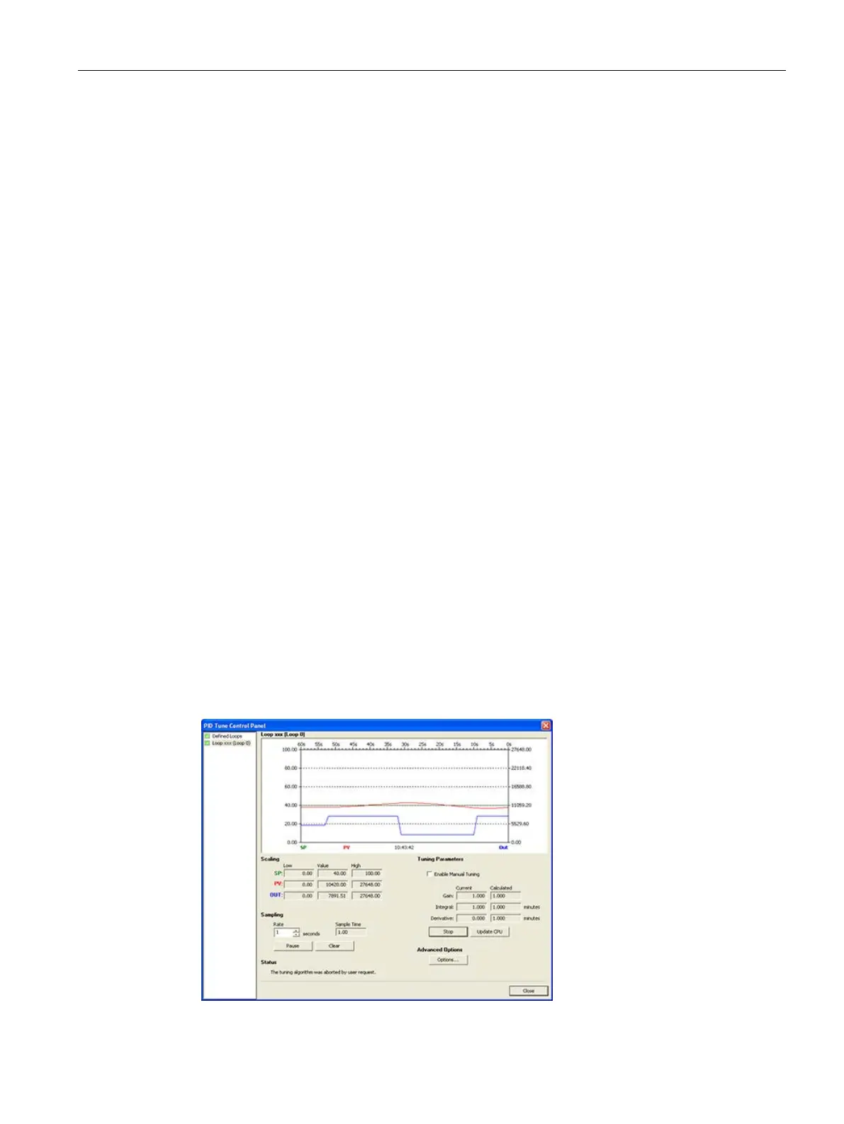
The following figure shows the output and process variable behaviors during an auto-tuning
sequence on a direct acting loop. You use the PID Tune control panel to initiate and monitor
the tuning sequence.

 Loading...


