Open loop motion control
12.6 Subroutines created by the Motion wizard for the Axis of Motion
S7-200 SMART
516 System Manual, 09/2015, A5E03822230-AC
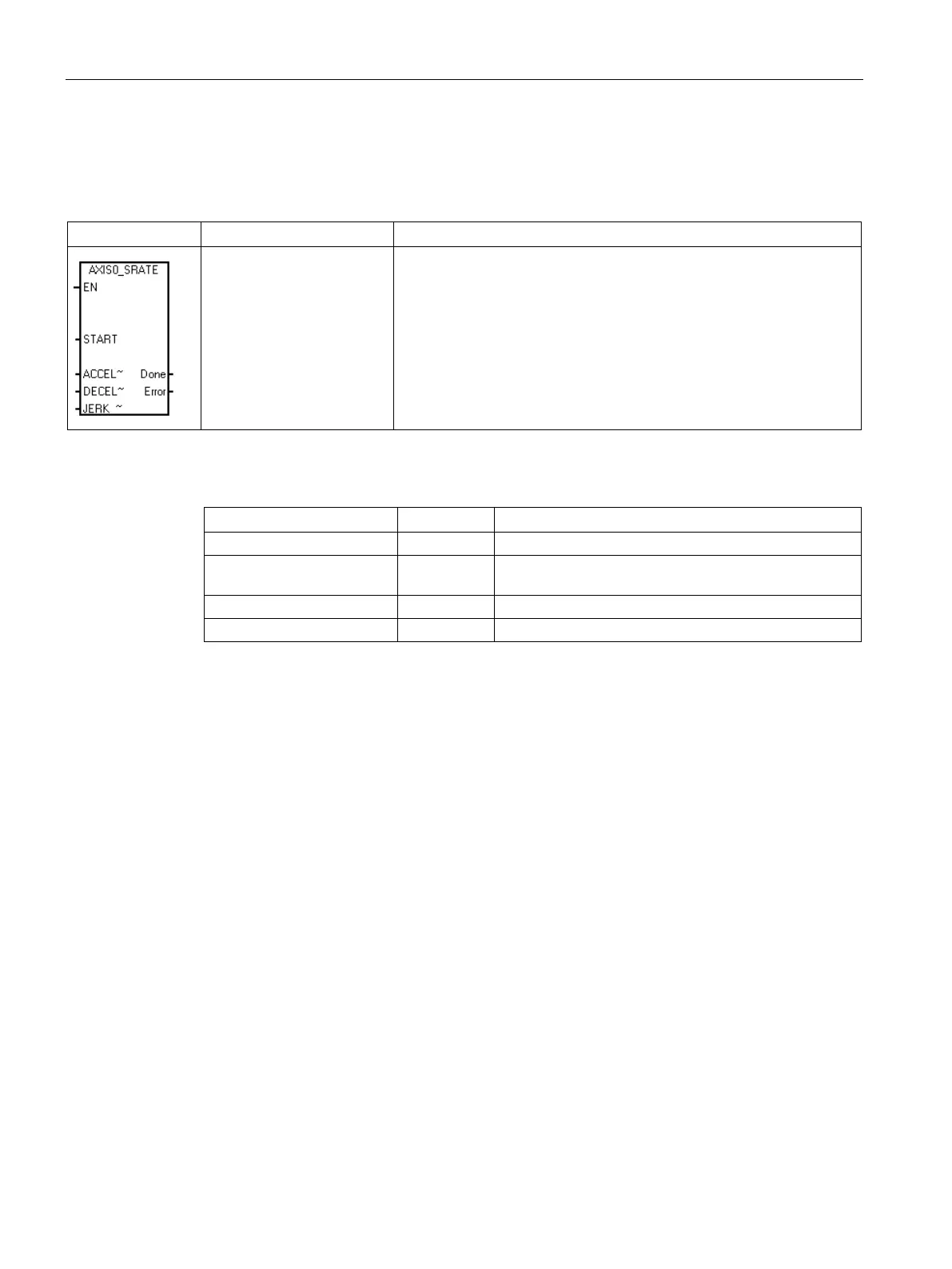
Table 12- 20 AXISx_SRATE
START, ACCEL_Time,
DECEL_Time,
JERK_Time, Done, Er-
ror
The AXISx_SRATE subroutine (Set Rate) commands the Axis of Mo-
tion to change the acceleration, deceleration, and jerk times.
Table 12- 21 Parameters for the AXISx_SRATE subroutine
I, Q, V, M, SM, S, T, C, L
ACCEL_Time,
DINT ID, QD, VD, MD, SMD, SD, LD, AC, *VD, *AC, *LD,
Done BOOL I, Q, V, M, SM, S, T, C, L
IB, QB, VB, MB, SMB, SB, LB, AC, *VD, *AC, *LD
Turn on the EN bit to enable the subroutine. Ensure that the EN bit stays on until the Done
bit signals that the execution of the subroutine has completed.
Turn on the START parameter to copy the new time values to the configuration/profile table
and sends a SRATE command to the Axis of Motion. For each scan when the START
parameter is on and the Axis of Motion is not currently busy, the subroutine sends an
SRATE command to the Axis of Motion. To ensure that only one command is sent, use an
edge detection element to pulse the START parameter on.
The ACCEL_Time, DECEL_Time, and JERK_Time parameters determine the new
acceleration time, deceleration time, and jerk time in milliseconds (ms).
The Done parameter turns on when the Axis of Motion completes this subroutine.
The Error parameter (Page 545) contains the result of this subroutine.

 Loading...


