EasyManua.ls Logo

Siemens Simatic S7 Series

Siemens Simatic S7 Series
726 pages
To Next Page IconTo Next Page
To Previous Page IconTo Previous Page
Loading...
Technical specifications
A.6 Digital signal boards
S7-200 SMART
System Manual, 09/2015, A5E03822230-AC
637
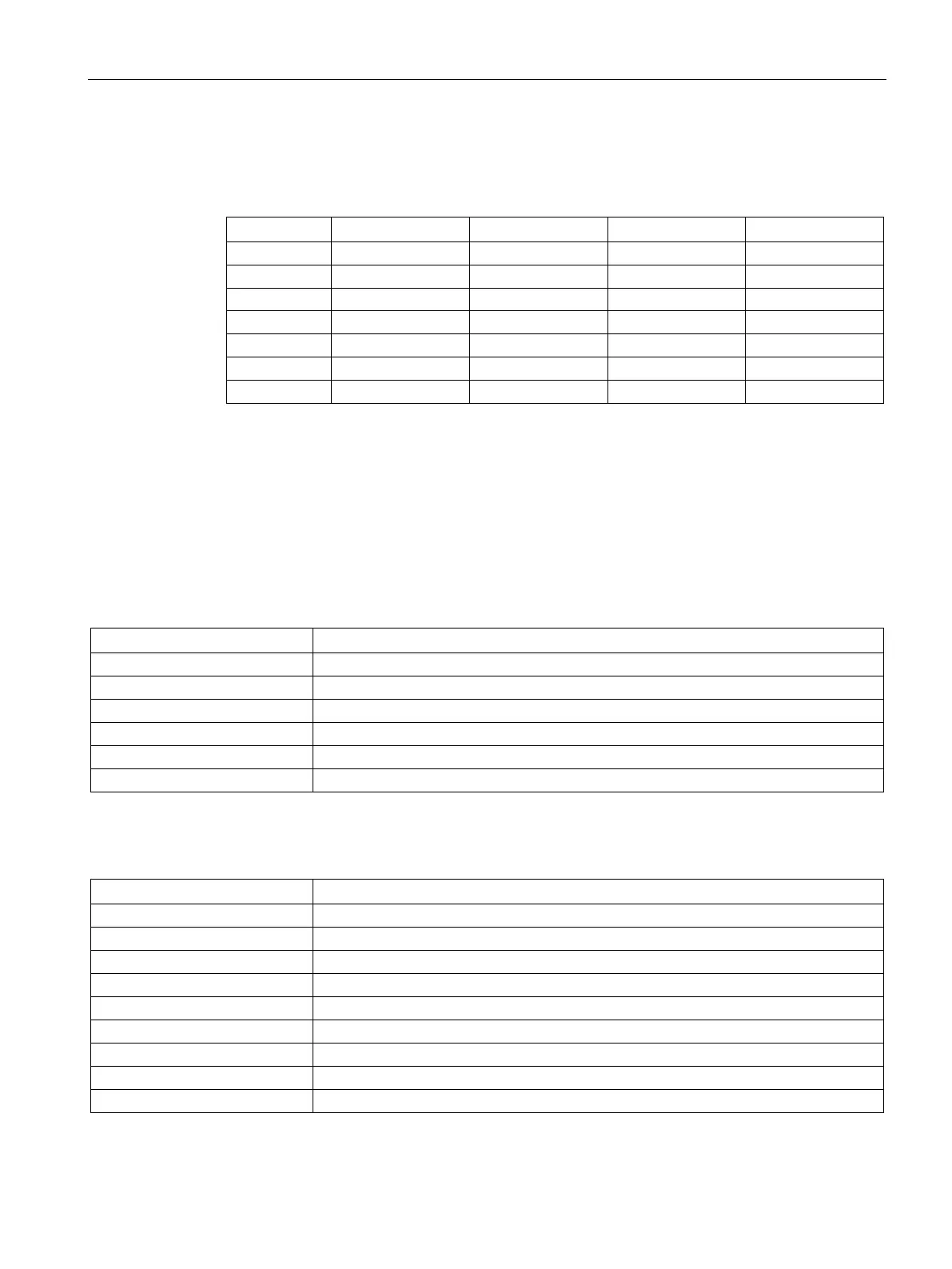
Table A- 124 Connector pin locations for EM AR04 RTD 4 x 16 bit (6ES7 288-3AR04-0AA0)
Pin
X10 (gold)
X11 (gold)
X12 (gold)
X13 (gold)
1
L+ / 24 V DC
No connection
No connection
No connection
2 M / 24 V DC No connection No connection No connection
3
Functional Earth
No connection
No connection
No connection
4
AI 0 M+/RTD
AI 1 M+/RTD
AI 2 M+/RTD
AI 3 M+/RTD
5
AI 0 M-/RTD
AI 1 M-/RTD
AI 2 M-/RTD
AI 3 M-/RTD
6
AI 0 I+/RTD
AI 1 I+/RTD
AI 2 I+.RTD
AI 3 I+/RTD
7
AI 0 I-/RTD
AI 1 I-/RTD
AI 2 I-/RTD
AI 3 I/-/RTD
A.6
Digital signal boards
A.6.1
SB DT04 digital input/output specifications
Table A- 125 General specifications
Technical data
SB Digital 2 x Inputs / 2 x Digital Outputs (DT04)
Article number
6ES7 288-5DT04-0AA0
Dimensions W x H x D (mm)
35 x 52.2 x 16
Weight
18.1 grams
Power dissipation
1.0 W
Current consumption (5 V DC)
50 mA
Current consumption (24 V DC)
4 mA / Input used
Table A- 126 Digital inputs
Technical data
SB Digital 2 x Inputs / 2 x Digital Outputs (DT04)
Number of inputs
2
Type
Sink (IEC Type 1 sink)
Rated voltage
24 V DC at 4 mA, nominal
Continuous permissible voltage
30 V DC max.
Surge voltage
35 V DC for 0.5 sec.
Logic 1 signal (min.)
15 V DC at 2.5 mA
Logic 0 signal (max.)
5 V DC at 1 mA
Isolation (field side to logic)
500 V AC for 1 minute
Isolation groups
1

Table of Contents

Other manuals for Siemens Simatic S7 Series

Related product manuals