Getting started
2.2 Creating the sample program
S7-200 SMART
System Manual, 09/2015, A5E03822230-AC
29
Note
The CPU list will show all of the CPUs regardless of Ethernet network class and subnet.
To make a connection to your CPU, your network interface card (NIC) and the CPU must be
on the same class of network and on the same subnet. You can either set up your network
interface card to match the default IP address of the CPU, or you can change the
IP address
of the CPU to match the network class and subnet of your network interface card.
See the "Configuring or changing an IP address for a CPU or device in your project" for
information about how to accomplish this.
Creating the sample program
Entering this example of a control program will help you understand how easy it is to use
STEP 7-Micro/WIN SMART. This program uses six instructions in three networks to create a
very simple, self-starting timer that resets itself.
For this example, you use the Ladder (LAD) editor to enter the instructions for the program.
The following example shows the complete program in both LAD and Statement List (STL).
The description column explains the logic for each network. The timing diagram shows the
operation of the program. There are no network comments in the STL program.
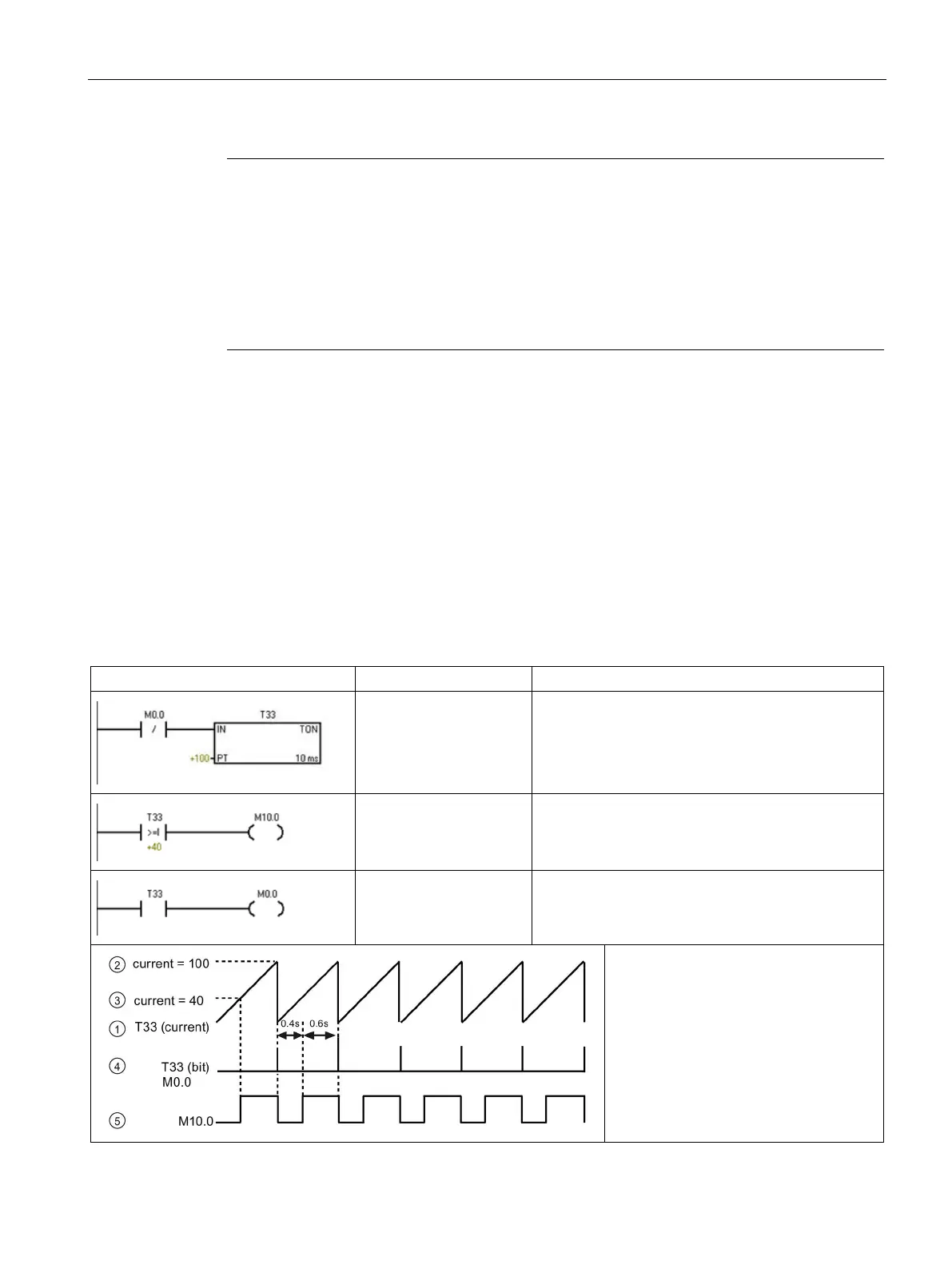
Table 2- 1 Sample program for getting started with STEP 7-Micro/WIN SMART
Network 1
LDN M0.0
TON T33, +100
10 ms timer T33 times out after (100 x 10 ms = 1 s)
M0.0 pulse is too fast to monitor with Status view.
Network 2
LDW>= T33, +40
= M10.0
Comparison becomes true at a rate that is visible
with Status view. Turn on M10.0 after (40 x 10 ms =
0.4 s) for a 40% OFF / 60% ON waveform.
T33 (bit) pulse is too fast to monitor with Status view.
Reset the timer through M0.0 after the (100 x 10 ms
= 1 s) period.
• ① T33 (current)
•
② Current = 100
•
③ Current = 40
•
④ T33 (bit) and M0.0
•
⑤ M10.0
 Loading...


