Program instructions
7.1 Bit logic
S7-200 SMART
162 System Manual, 09/2015, A5E03822230-AC
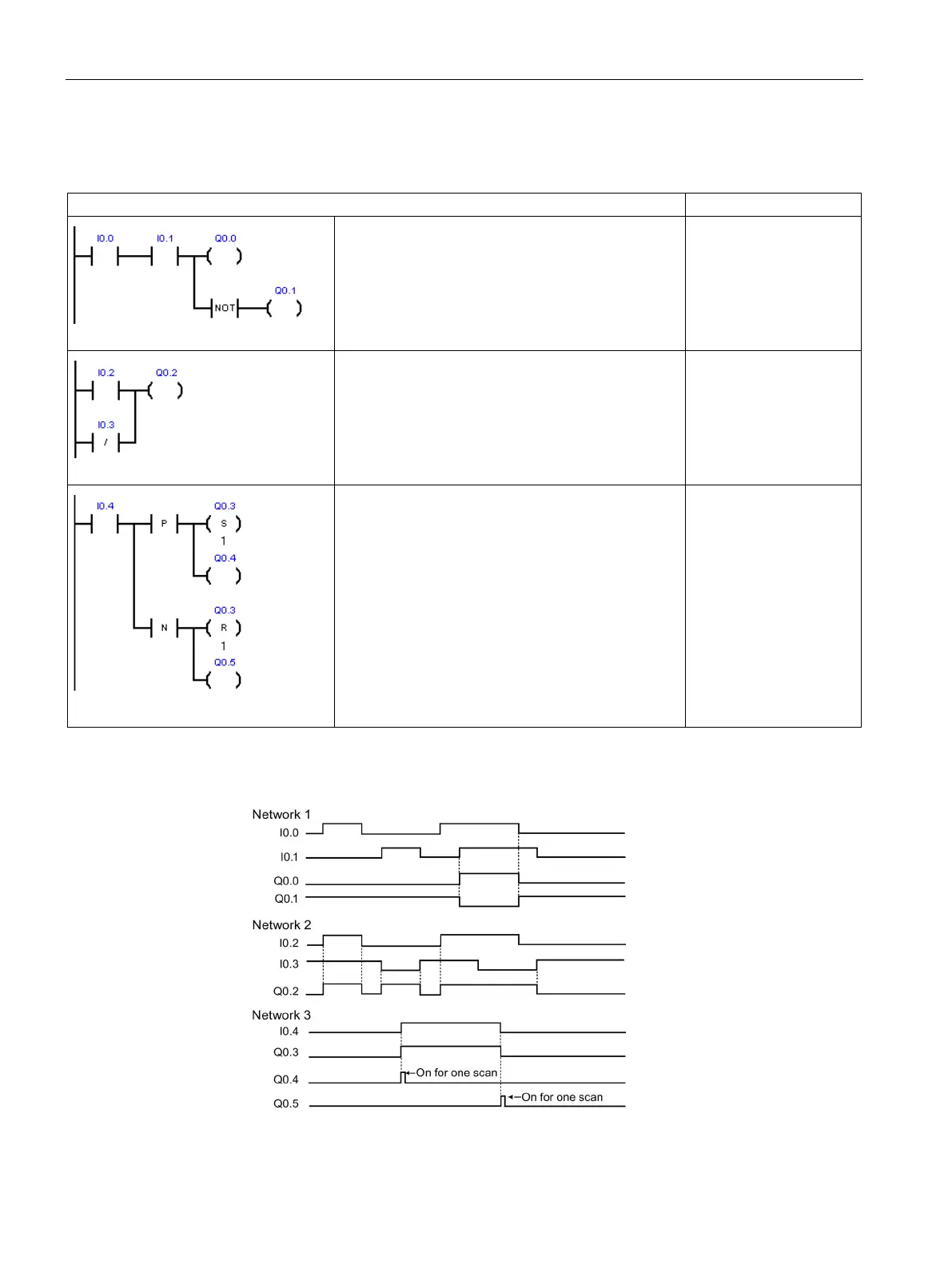
Normally-open contacts I0.0 AND I0.1 must be ON
(closed) to activate Q0.0. The NOT instruction acts
as an inverter. In RUN mode, Q0.0 and Q0.1 have
opposite logic states.
LD I0.0
A I0.1
= Q0.0
NOT
= Q0.1
(Normally-open contact I0.2 must be ON) or (Normal-
ly-closed contact I0.3 must be OFF), to activate
Q0.2. One or more parallel LAD branches (OR logic)
must be true to make the output active.
LD I0.2
ON I0.3
= Q0.2
A positive Edge Up input on a P contact or a nega-
tive Edge Down input on an N contact outputs a
pulse with a 1 scan cycle duration. In RUN mode, the
pulsed state changes of Q0.4 and Q0.5 are too fast
to be visible in program status view. The Set and
Reset outputs latch the pulse state into Q0.3 and
make the state change visible in program status
view.
LD I0.4
LPS
EU
S Q0.3, 1
= Q0.4
LPP
ED
R Q0.3, 1
= Q0.5
Run-mode timing for input example
 Loading...


