Special memory (SM) and system symbol names
D.6 SMB4: Interrupt queue overflow, run-time program error, interrupts enabled, freeport transmitter idle, and
value forced
S7-200 SMART
670 System Manual, 09/2015, A5E03822230-AC
SMB4: Interrupt queue overflow, run-time program error, interrupts
enabled, freeport transmitter idle, and value forced
Special memory byte 4 (SM4.0 - SM4.7) contains the interrupt queue overflow bits and a bit
(SM 4.4) that shows whether interrupts are enabled or disabled. These bits indicate either
that interrupts are occurring at a rate greater than can be processed or that interrupts were
disabled with the global interrupt disable instruction.
Other bits indicate:
● A run-time program error
● Freeport transmitter status
● If any PLC memory value is currently forced.
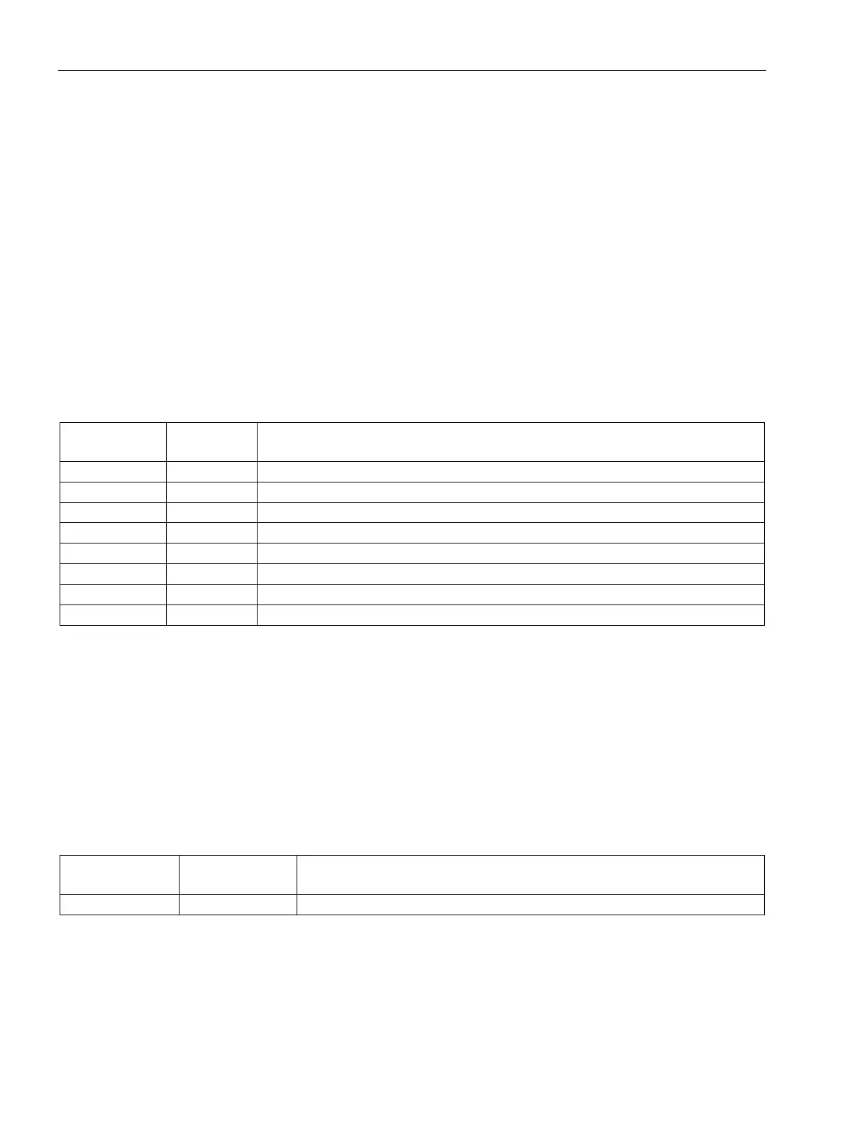
Table D- 5 SMB4 system status
1 = Communication interrupt queue has overflowed.
Input_Int_Ovr ** SM4.1 1 = Input interrupt queue has overflowed.
1 = Timed interrupt queue has overflowed.
1 = Run-time programming non-fatal error is detected.
1 = Interrupts are enabled.
1 = Port 0 transmitter is idle (0=transmission in progress).
1 = Port 1 transmitter is idle (0=transmission in progress).
1 = Any memory location is forced.
** Use status bits 4.0, 4.1, and 4.2 only inside an interrupt routine. These status bits are reset when the queue is emptied,
and control is returned to the main program.
Special Memory Byte 5 (SM5.0 - SM5.7) contains status bits which indicate error conditions
that were detected in the I/O system. These bits provide an overview of the I/O errors
detected.
Table D- 6 SMB5 I/O error status
This bit is set ON if any I/O errors are present.

 Loading...


