EasyManuals Logo

Siemens Simatic S7 Series System Manual

Siemens Simatic S7 Series
726 pages
To Next Page IconTo Next Page
To Previous Page IconTo Previous Page
Page #115 background imageLoading...
Page #115 background image
S7-200 SMART
System Manual, 09/2015, A5E03822230-AC
115
PLC device configuration
6
6.1
Configuring the operation of the PLC system
6.1.1
System block
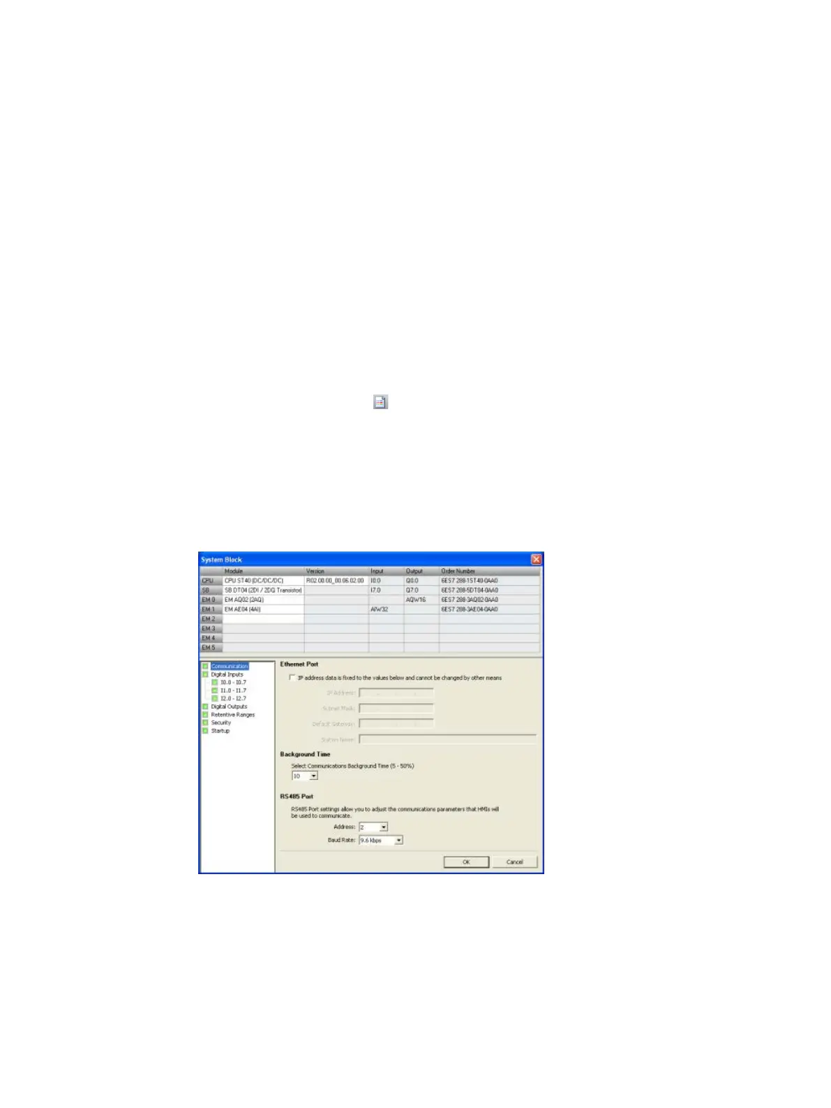
The system block provides configuration of the S7-200 SMART CPU, signal boards, and
expansion modules.
Use one of the following methods to view and edit the system block to set up CPU options:
Click the "System Block"
button on the navigation bar (Page 23).
Select "System Block" from the Component drop-down list (Page 23) in the Windows
area of the View menu ribbon strip.
Select the "System Block" node, then press Enter; or double-click the "System Block"
node in the project tree (Page 23).
STEP 7-Micro/WIN SMART opens the system block, and displays the configuration options
that are applicable for your CPU type.

Table of Contents

Other manuals for Siemens Simatic S7 Series

Questions and Answers:

Question and Answer IconNeed help?

Do you have a question about the Siemens Simatic S7 Series and is the answer not in the manual?

Siemens Simatic S7 Series Specifications

General IconGeneral
CPUVaries by model (e.g., S7-300, S7-400, S7-1200, S7-1500)
Communication InterfacesPROFIBUS, PROFINET, Ethernet, MPI
ProgrammingTIA Portal, STEP 7
Programming LanguagesLAD, FBD, STL, SCL, GRAPH
I/O ModulesDigital, Analog, Specialty modules available
Operating Temperature0°C to 60°C (standard models)
MountingDIN rail mounting
Operating Voltage24V DC or 120/230V AC (varies by model)
Protection ClassIP20 (standard models)
MemoryVaries depending on the S7 model. Includes work memory (RAM) for program execution, load memory (EEPROM or Flash) for program storage, and system memory for operating system functions. Memory sizes range from kilobytes to megabytes.

Related product manuals