Program instructions
7.7 Pulse output
S7-200 SMART
System Manual, 09/2015, A5E03822230-AC
247
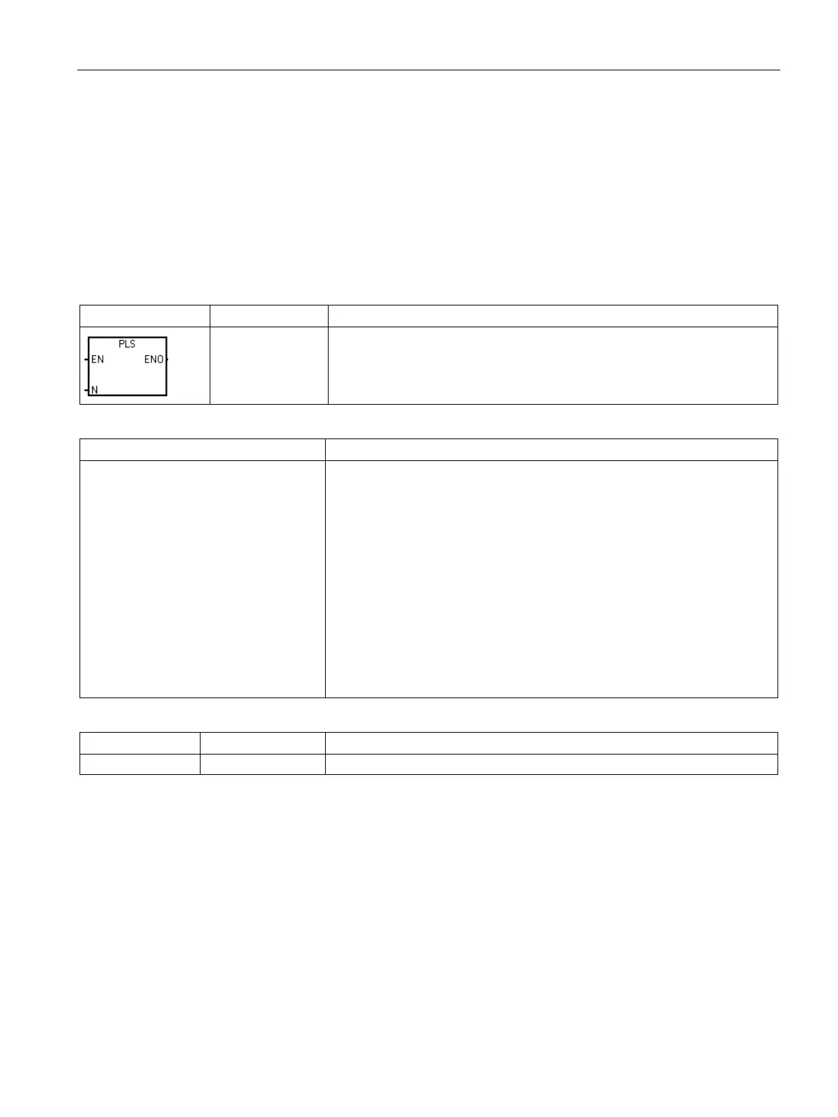
Pulse output instruction (PLS)
The Pulse output (PLS) instruction controls the Pulse train output (PTO) and Pulse width
modulation (PWM) functions available on the high-speed outputs (Q0.0, Q0.1, and Q0.3).
When using PWM, you can use an optional wizard to create the PWM instructions.
You can use the PLS instruction to create up to three PTO or PWM opera-
tions. PTO allows the user to control the frequency and number of pulses for a
square wave (50% duty cycle) output. PWM allows the user control of a fixed
cycle time output with a variable duty cycle.
Error conditions with ENO = 0
• 0005H: Simultaneous HSC/PLS
• 000DH: Attempt to redefine pulse
output while it is active
• 000EH: Number of PTO profile seg-
ments was set to 0
• 0017H: Attempt to assign resource for
PTO/PWM that is already assigned to
motion control
• 001BH: Attempt to change time base
on enabled PWM
• 0090H: N is not 0, 1, or 2.
• 0091H: Range error
None
Constant: 0 (= Q0.0), 1 (= Q0.1), or 2 (= Q0.3)
The CPU has three PTO/PWM generators (PLS0, PLS1, and PLS2) that create either a
high-speed pulse train or a pulse width modulated waveform. PLS0 is assigned to digital
output point Q0.0, PLS1 is assigned to digital output point Q0.1, and PLS2 is assigned to
digital output point Q0.3. A designated special memory (SM) location stores the following
data for each generator: a PTO status byte (8-bit value), a control byte (8-bit value), a cycle
time or frequency (unsigned 16-bit value), a pulse width value (unsigned 16-bit value), and a
pulse count value (unsigned 32-bit value).

 Loading...


