Open loop motion control
12.1 Using the PWM output
S7-200 SMART
System Manual, 09/2015, A5E03822230-AC
483
Use one of the following methods to open the PWM wizard:
● Click the "PWM" button from the Wizards area of the Tools menu.
● Open the Wizards folder in the project tree and double-click "PWM", or select "PWM" and
press the Enter key.
1. Select a pulse generator.
2. Change the name of a PWM channel, if required.
3. Configure the PWM channel output time base.
4. Generate project components.
5. Use the PWMx_RUN subroutine to control the duty cycle of your PWM output.
Note
PWM channels are hard
-coded to specific outputs:
PWM0 is assigned to Q0.0.
PWM1 is assigned to Q0.1.
PWM2 is assigned to Q0.3.
To simplify the use of Pulse Width Modulation (PWM) control in your application,
STEP 7-Micro/WIN SMART provides a PWM wizard (Page 482) to configure your on-board
PWM generators and control the duty cycle of a PWM output.
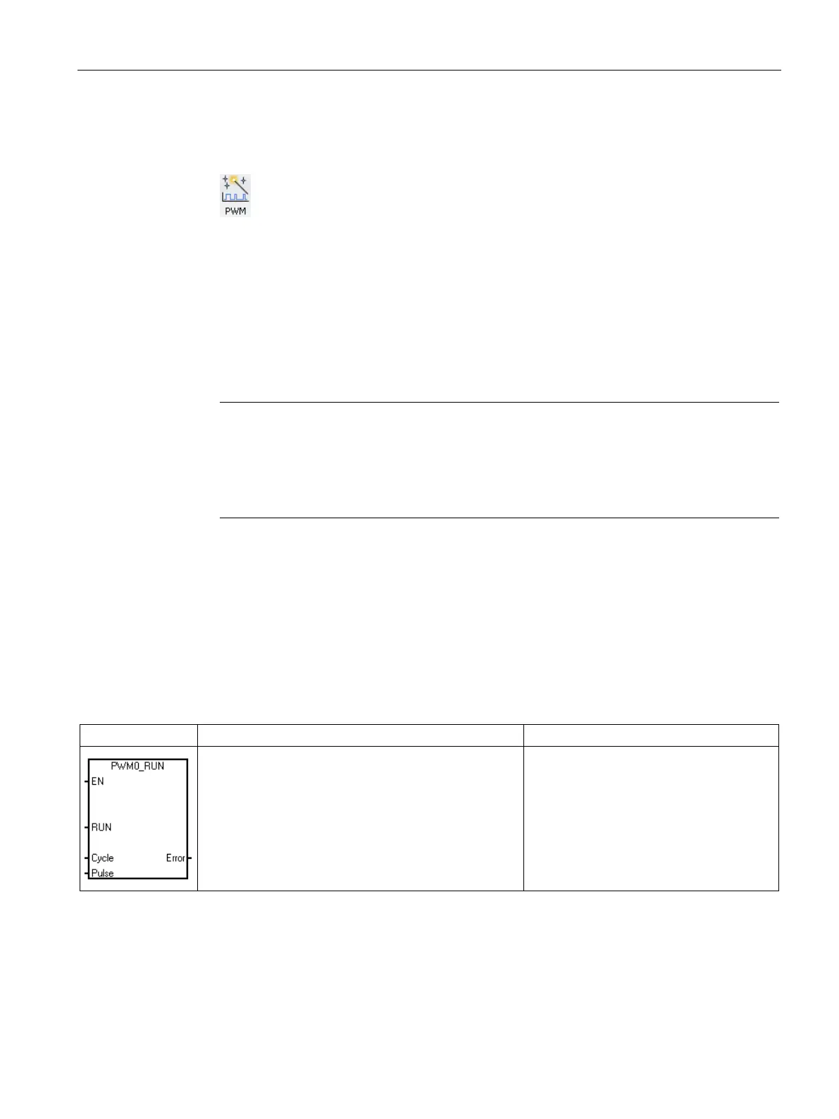
The PWMx_RUN subroutine is used to execute PWM under program control.
CALL PWMx_RUN, Cycle, Pulse, Error
The PWMx_RUN subroutine allows you to
control the duty cycle of the output by vary-
ing the pulse width from 0 to the pulse
width of the cycle time.

 Loading...


