Open loop motion control
12.6 Subroutines created by the Motion wizard for the Axis of Motion
S7-200 SMART
514 System Manual, 09/2015, A5E03822230-AC
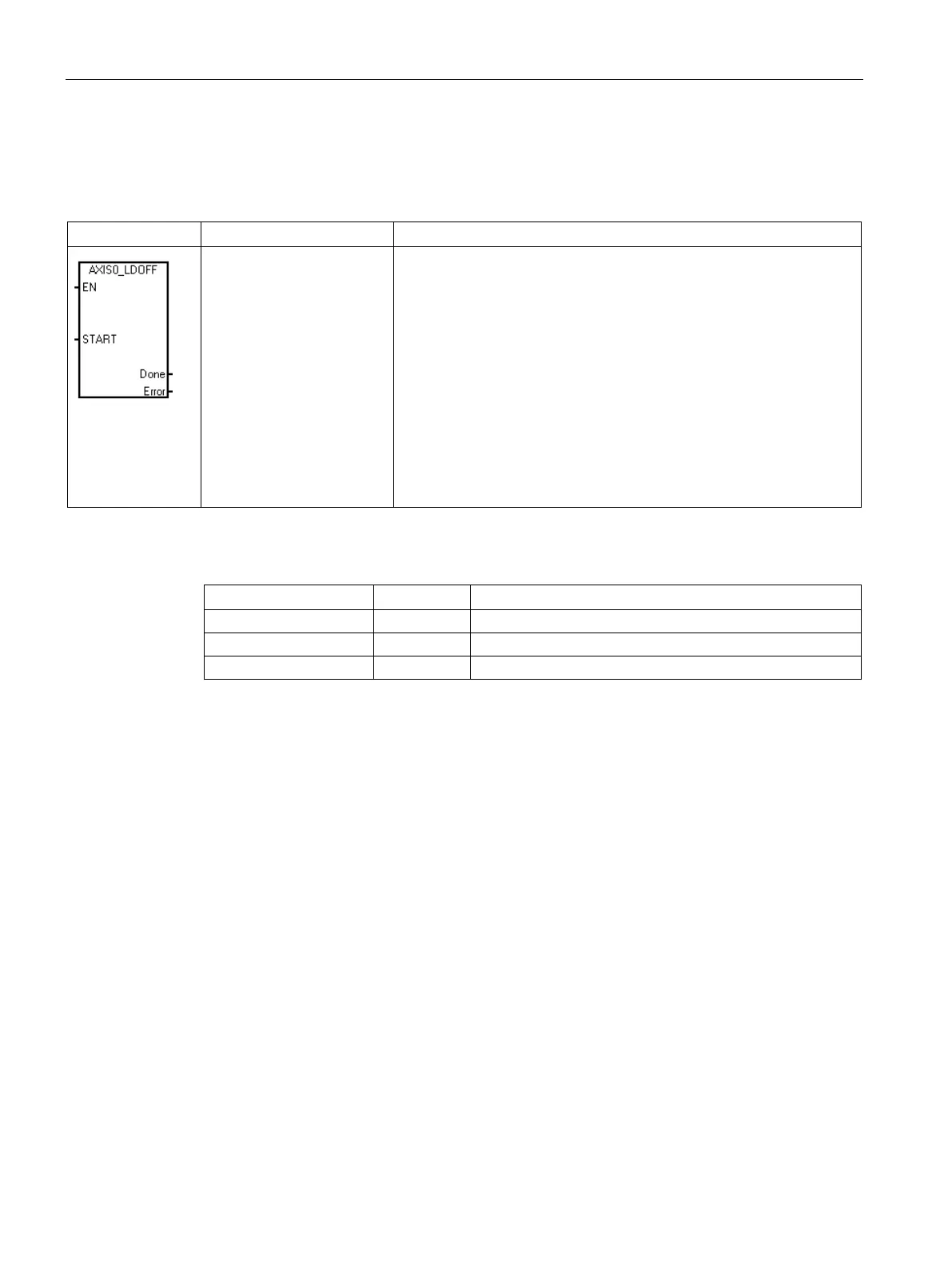
Table 12- 16 AXISx_LDOFF
START, Done, Error
The AXISx_LDOFF subroutine (Load Reference Point Offset) estab-
lishes a new zero position that is at a different location from the refer-
ence point position.
Before executing this subroutine, you must first determine the position
of the reference point. You must also move the machine to the starting
position. When the subroutine sends the LDOFF command, the Axis of
Motion computes the offset between the starting position (the current
position) and the reference point position. The Axis of Motion then
stores the computed offset to the RP_OFFSET parameter and sets the
current position to 0. This establishes the starting position as the zero
position.
In the event that the motor loses track of its position (such as on loss of
power or if the motor is repositioned manually), you can use the AX-
ISx_RSEEK subroutine to re-establish the zero position automatically.
Table 12- 17 Parameters for the AXISx_LDOFF subroutine
I, Q, V, M, SM, S, T, C, L, Power Flow
I, Q, V, M, SM, S, T, C, L
IB, QB, VB, MB, SMB, SB, LB, AC, *VD, *AC, *LD
Turn on the EN bit to enable the subroutine. Ensure that the EN bit stays on until the Done
bit signals that the execution of the subroutine has completed.
Turn on the START parameter to send a LDOFF command to the Axis of Motion. For each
scan when the START parameter is on and the Axis of Motion is not currently busy, the
subroutine sends a LDOFF command to the Axis of Motion. To ensure that only one
command is sent, use an edge detection element to pulse the START parameter on.
The Done parameter turns on when the Axis of Motion completes this subroutine.
The Error parameter (Page 545) contains the result of this subroutine.

 Loading...


