Program instructions
7.1 Bit logic
S7-200 SMART
160 System Manual, 09/2015, A5E03822230-AC
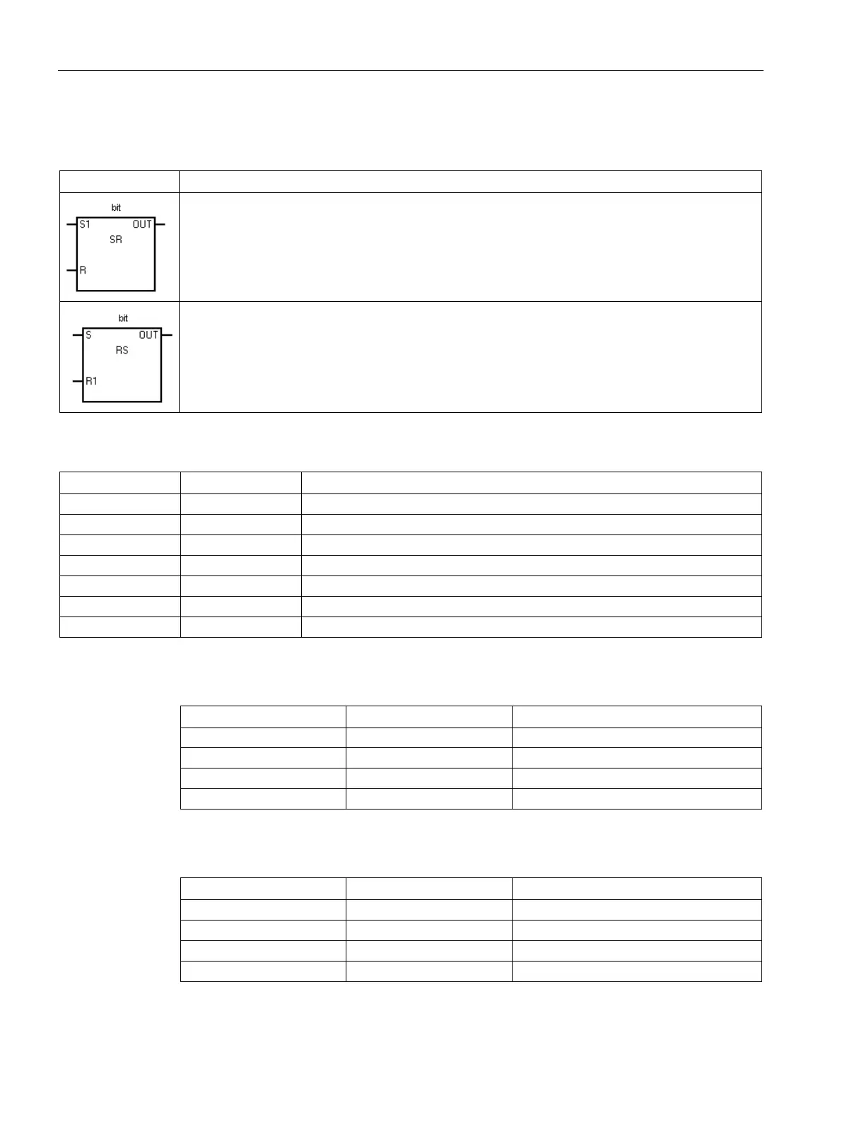
Set and reset dominant bistable
The bit parameter assigns the Boolean address that is set or reset. The optional OUT connection
reflects the signal state of the Bit parameter.
(Set dominant bistable) is a latch where the set dominates. If the set (S1) and reset (R) signals
are both true, the output (OUT) is true.
(Reset dominant bistable) is a latch where the reset dominates. If the set (S) and reset (R1) sig-
nals are both true, the output (OUT) is false.
I, Q, V, M, SM, S, T, C, L, Logic flow
I, Q, V, M, SM, S, T, C, L, Logic flow
I, Q, V, M, SM, S, T, C, L, Logic flow
0 0 Previous state
1 0 1
t
 Loading...


