Program instructions
7.6 Counters
S7-200 SMART
216 System Manual, 09/2015, A5E03822230-AC
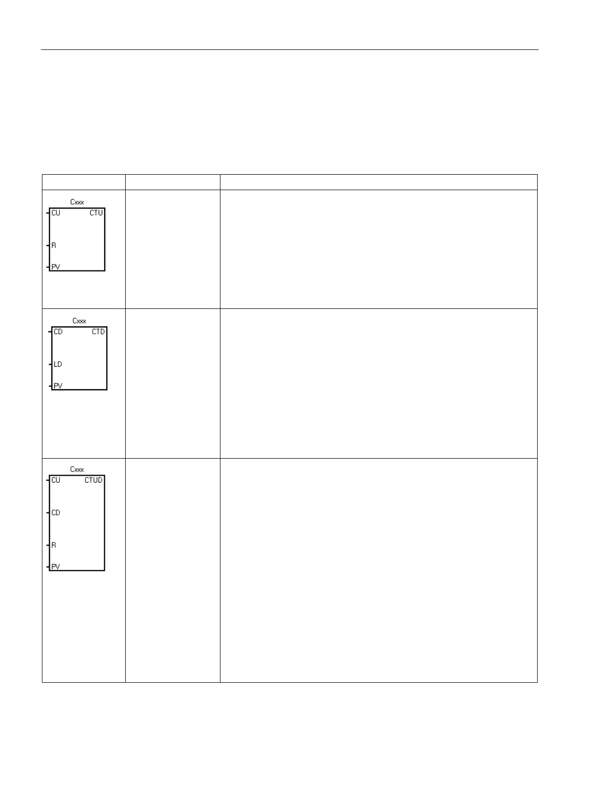
The
count up instruction counts up from the current value
each time the count up CU input makes the transition from OFF to ON. When
the current value Cxxx is greater than or equal to the preset value PV, the
counter bit Cxxx is set ON. The current count value is reset when the reset
input R is set ON, or when the reset instruction is executed for the Cxxx ad-
dress. The counter stops counting when it reaches the maximum value
32,767.
R reset input is the top of stack value
CU count up input is loaded in the
The
count down instruction counts down from the current
value of that counter each time the CD count down input makes the transition
from OFF to ON. When the current value Cxxx is equal to 0, the counter bit
Cxxx turns ON. The counter resets the counter bit Cxxx and loads the current
value with the preset value PV when the LD load input is set ON. The counter
stops upon reaching zero, and the counter bit Cxxx is set ON.
LD load input is the top of stack value. CD count down input value is
loaded in the second stack level
The
count up/down instruction counts up each time the CU
count up input makes the transition from OFF to ON, and counts down each
time the CD count down input makes the transition from OFF to ON. The
current value Cxxx of the counter maintains the current count. The PV preset
value is compared to the current value each time the counter instruction is
executed.
Upon reaching maximum value 32,767, the next rising edge at the count up
input causes the current count to wrap around to the minimum value -32,768.
On reaching the minimum value -32,768, the next rising edge at the count
down input causes the current count to wrap around to the maximum value
32,767.
When the current value Cxxx is greater than or equal to the PV preset value,
the counter bit Cxxx is set ON. Otherwise, the counter bit is OFF. The counter
is reset when the R reset input is set ON, or when the Reset instruction is
executed for the Cxxx address.
R reset input is the top of stack value. CD count down input value is
loaded in the second stack level. CU count Up input value is loaded in the

 Loading...


