Program instructions
7.6 Counters
S7-200 SMART
System Manual, 09/2015, A5E03822230-AC
217
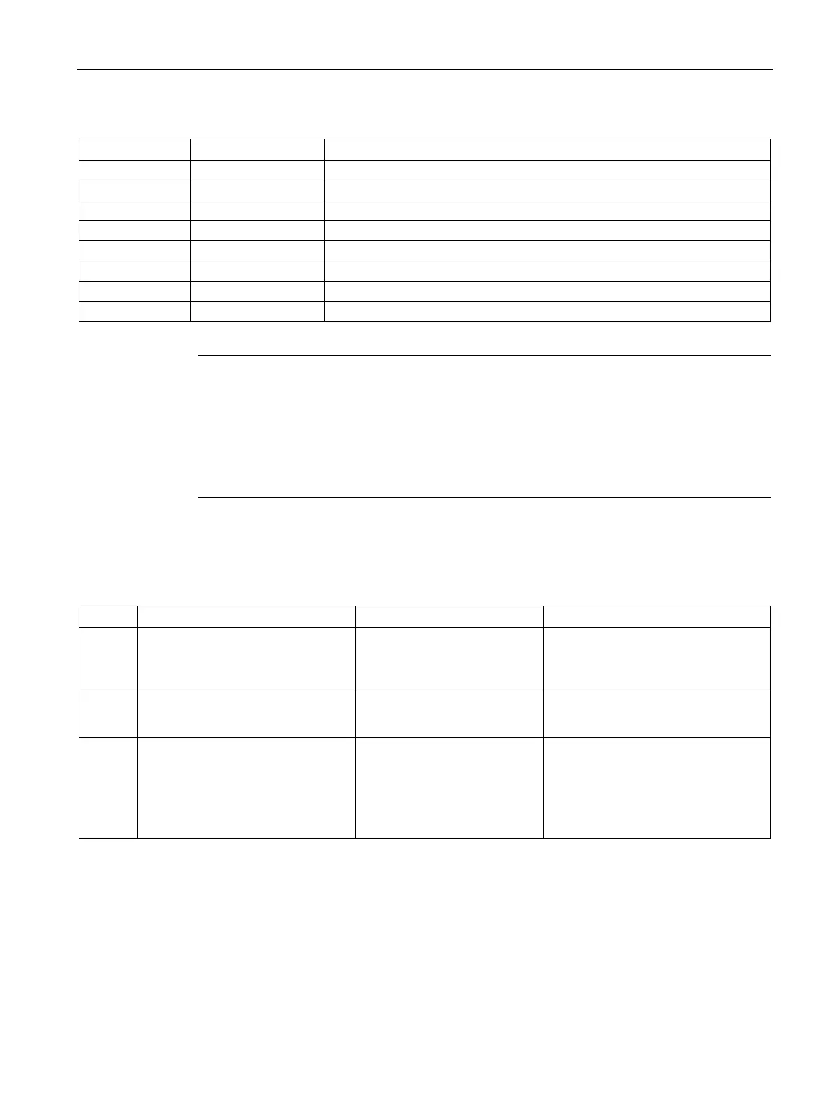
CU, CD (LAD) BOOL Power flow
I, Q, V, M, SM, S, T, C, L, Logic flow
I, Q, V, M, SM, S, T, C, L, Logic flow
I, Q, V, M, SM, S, T, C, L, Logic flow
IW, QW, VW, MW, SMW, SW, LW, T, C, AC, AIW, *VD, *LD, *AC, Constant
Note
Since there is one current value for each counter,
do not assign the same counter number to
more than one counter. (Up Counters, Up/Down Counters, and Down counters with the
same number access the same current value.)
When you reset a counter using the Reset instruction, the counter bit is reset and the
c
ounter current value is set to zero. Use the counter number to reference both the current
value and the counter bit of that counter.
Configuring the retentive ranges - system block configuration
CTU
• CU increments the current value.
• Current value continues to incre-
ment until it reaches 32,767.
The counter bit is set ON when:
Current value >= Preset
• Counter bit is OFF.
• Current value can be retained
1
CTD
• CD decrements the current value
until the current value reaches 0.
The counter bit is set ON when:
Current value = 0
• Counter bit is OFF.
• Current value can be retained
1
CTUD
• CU increments the current value.
• CD decrements the current value.
• Current value continues to incre-
ment or decrement until the coun-
ter is reset.
The counter bit is set ON when:
Current value >= Preset
• Counter bit is OFF.
• Current value can be retained
1
1
You can select the current value for the counter to be retentive, but not the counter bit value.

 Loading...


