EasyManuals Logo

Siemens Simatic S7 Series System Manual

Siemens Simatic S7 Series
726 pages
To Next Page IconTo Next Page
To Previous Page IconTo Previous Page
Page #92 background imageLoading...
Page #92 background image
Programming concepts
5.3 Creating your user program
S7-200 SMART
92 System Manual, 09/2015, A5E03822230-AC
5.3.2
Using STEP 7-Micro/WIN SMART user interface
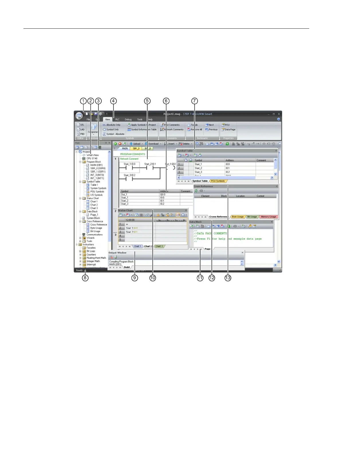
The STEP 7-Micro/WIN SMART user interface appears below. Note that each editing
window can be docked or floated and arranged on the screen as you choose. You can
display each window separately, as shown below, or you can combine windows such that
each one is accessible from a separate tab:
Quick access toolbar (Page 93)
Project tree (Page 93)
Navigation bar (Page 93)
Menus (Page 93)
Program editor (Page 93)
Symbol information table (Page 100)
Symbol table (Page 100)
Status bar (Page 93)
Output window (Page 93)
Status chart (Page 460)
Variable table (Page 104)
Data block (Page 97)
Cross reference (Page 454)

Table of Contents

Other manuals for Siemens Simatic S7 Series

Questions and Answers:

Question and Answer IconNeed help?

Do you have a question about the Siemens Simatic S7 Series and is the answer not in the manual?

Siemens Simatic S7 Series Specifications

General IconGeneral
CPUVaries by model (e.g., S7-300, S7-400, S7-1200, S7-1500)
Communication InterfacesPROFIBUS, PROFINET, Ethernet, MPI
ProgrammingTIA Portal, STEP 7
Programming LanguagesLAD, FBD, STL, SCL, GRAPH
I/O ModulesDigital, Analog, Specialty modules available
Operating Temperature0°C to 60°C (standard models)
MountingDIN rail mounting
Operating Voltage24V DC or 120/230V AC (varies by model)
Protection ClassIP20 (standard models)
MemoryVaries depending on the S7 model. Includes work memory (RAM) for program execution, load memory (EEPROM or Flash) for program storage, and system memory for operating system functions. Memory sizes range from kilobytes to megabytes.

Related product manuals