Program instructions
7.1 Bit logic
S7-200 SMART
System Manual, 09/2015, A5E03822230-AC
151
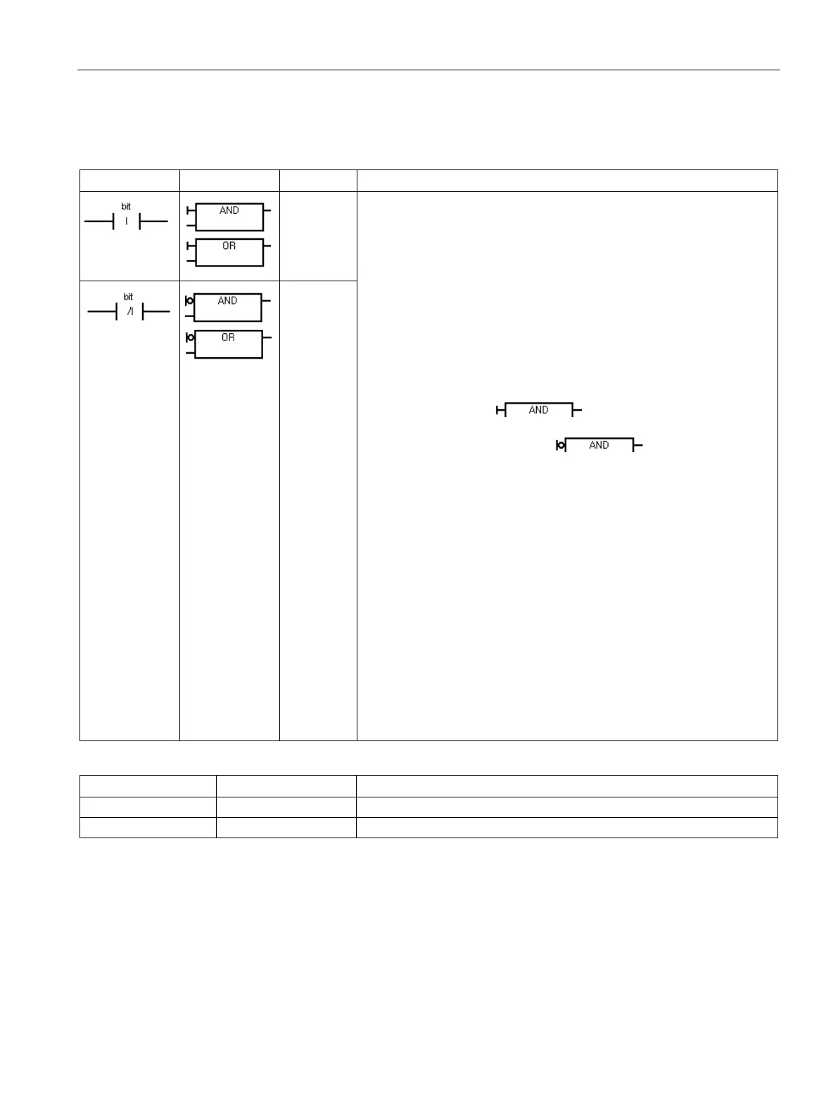
AI bit
OI bit
The immediate instruction obtains the physical input value when the
instruction is executed, but the process image register is not updated. An
immediate contact does not wait on the PLC scan cycle to update; it
updates immediately.
The Normally Open Immediate contact is closed (ON) when the physical
input point (bit) state is 1.
The Normally Closed Immediate contact is closed (ON) when the physi-
cal input point (bit) state is 0.
: Normally open and normally closed immediate instructions are
represented by contacts.
: Normally open immediate instructions are represented by the verti-
cal immediate indicator in front of an input connection.
The Normally closed immediate instruction is represented by the imme-
diate indicator and negation circle
in front of an input
connection.
The immediate indicator cannot be used when a logic flow connection is
used instead of a physical input ( I ) bit address.
FBD box instructions can be used to evaluate physical signals in the
same manner as ladder contacts. The number of inputs for the AND/OR
boxes can be expanded to a maximum of 31 inputs.
: The Normally Open Immediate contact is represented by the LDI
(Load Immediate), AI (AND Immediate), and OI (OR Immediate) instruc-
tions. These instructions load, AND, or OR the physical input value with
the top of the logic stack.
A normally Closed Immediate contact is represented by the LDNI (Load
NOT Immediate), ANI (AND NOT Immediate), and ONI (OR NOT Imme-
diate) instructions. These instructions immediately load, AND, or OR the
logical NOT of the value of the physical input value with the top of the
logic stack.
t
ANI bit
ONI bit

 Loading...


