Program instructions
7.1 Bit logic
S7-200 SMART
System Manual, 09/2015, A5E03822230-AC
163
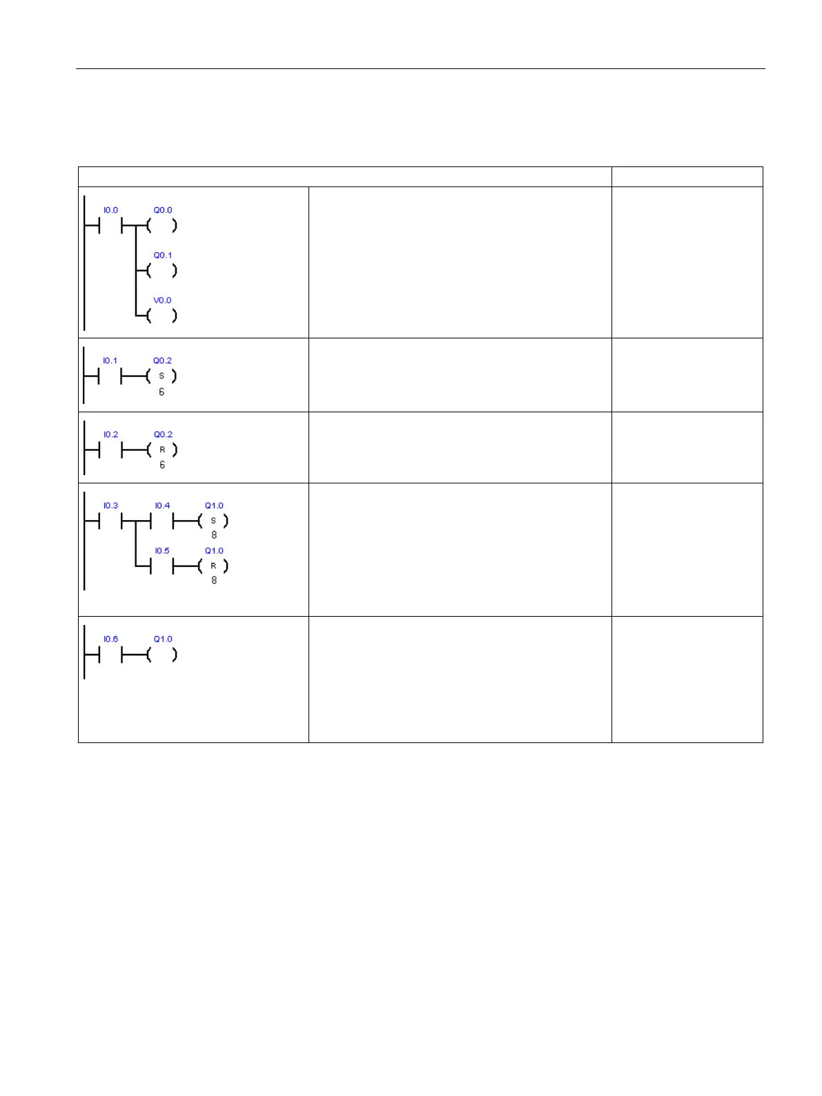
Bit logic output examples
Output instructions assign bit values to external I/O
(I, Q) and internal memory (M, SM, T, C, V, S, L).
LD I0.0
= Q0.0
= Q0.1
= V0.0
Set a sequential group of 6 bits to a value of 1. Spec-
ify a starting bit address and how many bits to set.
The program status indicator for Set is ON when the
value of the first bit (Q0.2) is 1.
LD I0.1
S Q0.2, 6
Reset a sequential group of 6 bits to a value of 0.
Specify a starting bit address and how many bits to
reset. The program status indicator for Reset is ON
when the value of the first bit (Q0.2) is 0.
LD I0.2
R Q0.2, 6
Sets and resets 8 output bits (Q1.0 to Q1.7) as a
group.
LD I0.3
LPS
A I0.4
S Q1.0, 8
LPP
A I0.5
The Set and Reset instructions perform the function
of a latched relay. To isolate the Set/Reset bits,
make sure they are not overwritten by another as-
signment instruction. In this example, Network 4 sets
and resets eight output bits (Q1.0 to Q1.7) as a
group. In RUN mode, Network 5 can overwrite the
Q1.0 bit value and control the Set/Reset program
status indicators in Network 4.
LD I0.6
= Q1.0

 Loading...


