Debugging and troubleshooting
10.3 Using a status chart to monitor your program
S7-200 SMART
460 System Manual, 09/2015, A5E03822230-AC
Using a status chart to monitor your program
In a status chart, you can enter addresses or defined symbol names to monitor or modify the
status of program inputs, outputs, or variables by displaying the current values. The status
chart also allows you to force or change the values of the process variables. You can create
multiple status charts in order to view elements from different portions of your program.
You can display timer and counter values as either bits or words. If you display a timer or
counter value as a bit, you see the output status of the instruction (0 or 1). If you display a
timer or counter value as a word, you see the current value of the timer or counter.
To create a new status chart, make sure that Chart Status and Program Status is off and use
one of these methods to create a new chart:
● From the project tree, right-click the Status Chart folder and select the context menu
command
.
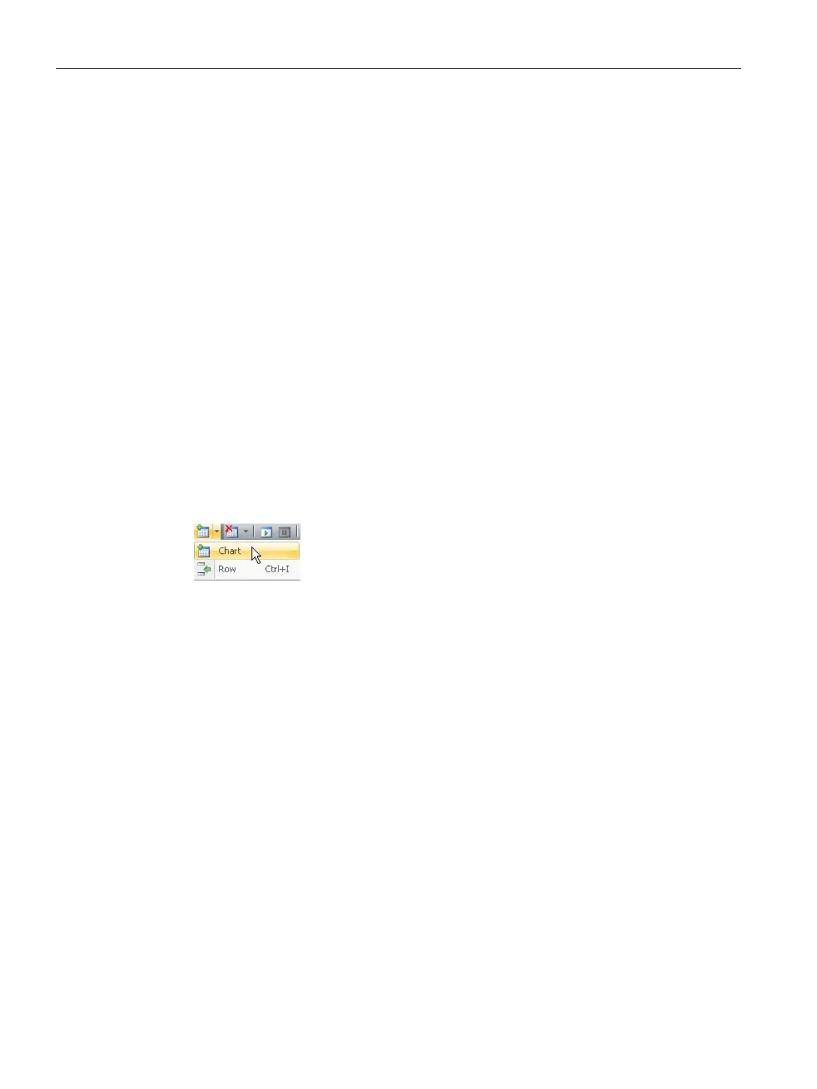
● From the Insert area of the Edit menu ribbon strip, click the down arrow beneath "Object"
and select "Chart" from the drop-down menu.
● From a status chart tab in the status chart editor, or from any cell in an existing status
chart, right-click and select the context menu command
.
● From the status chart toolbar, click the insert button and select "Chart".
After you successfully insert a new status chart, the new chart appears under "Status Chart"
in the project tree and a new tab appears at the bottom of the Status Chart window.
Opening an existing chart
If the status chart editor is not open, you can open an existing status chart from the project
tree, navigation bar, or from the Component drop-down list in the Windows area of the View
menu. If the status chart editor is open, you can click a status chart tab in the editor to switch
to that status chart.

 Loading...


