Libraries
9.3 Modbus library instructions
S7-200 SMART
446 System Manual, 09/2015, A5E03822230-AC
Parameter
sets the number of I and Q points available to Modbus addresses 0xxxx
and 1xxxx at values of 0 to 256. A value of 0 disables all reads and writes to the inputs and
outputs. The suggested value for MaxIQ is 256.
Parameter
sets the number of word input (AI) registers available to Modbus address
3xxxx at values of 0 to 56. A value of 0 disables reads of the analog inputs. The suggested
value for MaxAI to allow access to all of the CPU analog inputs, is as follows:
● 0 for CPU CR40
● 56 for all other CPU models
Parameter
sets the number of word holding registers in V memory available to
Modbus address 4xxxx or 4yyyyy. For example, if you want to allow Modbus master access
for 2000 bytes of V memory, set MaxHold to a value of 1000 words (holding registers).
Parameter
is the address of the start of the holding registers in V memory. This
value is generally set to VB0, so the parameter HoldStart is set to &VB0 (address of VB0).
Other V memory addresses can be specified as the starting address for the holding registers
to allow VB0 to be used elsewhere in the project. The Modbus master has access to
MaxHold number of words of V memory starting at HoldStart.
When the MBUS_INIT instruction completes, the Done output is turned ON.
The Error output byte contains the result of executing the instruction. This output is only valid
if Done is ON. If Done is OFF, the error parameter is not changed.
Modbus slave execution error codes (Page 448)
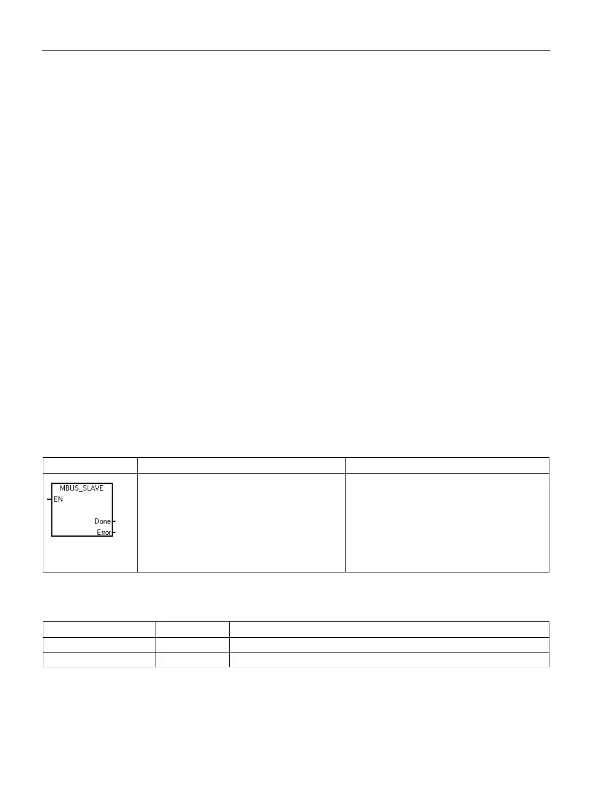
Table 9- 29 MBUS_SLAVE instruction
CALL MBUS_SLAVE, Done, Error
The MBUS_SLAVE instruction is used to ser-
vice a request from the Modbus master and
must be executed every scan to allow it to
check for and respond to Modbus requests.
The instruction is executed on each scan when
the EN input is ON.
The MBUS_SLAVE instruction has no input
Table 9- 30 Parameters for the MBUS_SLAVE Instruction
I, Q, M, S, SM, T, C, V, L
VB, IB, QB, MB, SB, SMB, LB, AC, *VD, *AC, *LD
The Done output is ON when the MBUS_SLAVE instruction responds to a Modbus request.
The Done output is OFF, if there was no request serviced.

 Loading...


