Program instructions
7.1 Bit logic
S7-200 SMART
System Manual, 09/2015, A5E03822230-AC
159
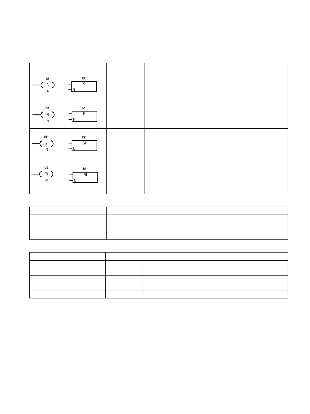
Set, reset, set immediate, and reset immediate functions
The Set (S) and Reset (R) instructions set (ON) or reset (OFF) the
number of bits (N), starting at the address (bit). You can set or
reset from 1 to 255 bits.
If the Reset instruction specifies either a timer bit (T address) or
counter bit (C address), the instruction resets the timer or counter
bit and clears the current value of the timer or counter.
The Set Immediate and Reset Immediate instructions immediately
set (ON) or immediately reset (OFF) the number of points (N),
starting at address (bit). You can set or reset from 1 to 255 points
immediately.
The "I" indicates an immediate reference; when the instruction is
executed, the new value is written to both the physical output point
and the corresponding process image register location. This differs
from the non-immediate references, which write the new value to
the process image register only.
Non-fatal errors with ENO = 0
• N = 0 (zero)
• 0006H Indirect address
• 0091H Operand out of range
None
I, Q, V, M, SM, S, T, C, L
IB, QB, VB, MB, SMB, SB, LB, AC, Constant, *VD, *AC, *LD
I, Q, V, M, SM, S, T, C, L, Logic flow
Bit logic input examples (Page 162)
Bit logic output examples (Page 163)

 Loading...


