Open loop motion control
12.7 Using the AXISx_ABSPOS subroutine to read the absolute position from a SINAMICS servo drive
S7-200 SMART
524 System Manual, 09/2015, A5E03822230-AC
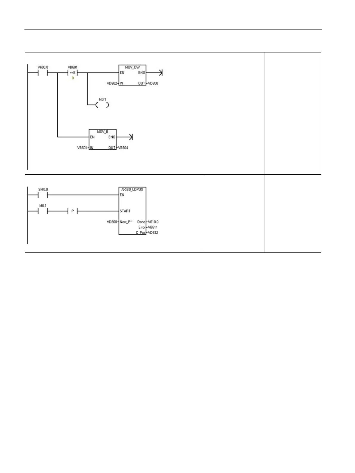
Network 2:
When the operation is
done, capture the error
code and also capture
the servo position, if no
error.
Network 3:
Update the current
position in this Axis of
Motion with the cap-
tured servo position
value.
CALL AXIS0_LDPOS,
L63.7, VD800,
V610.0, VB611,
VD612
Interconnections
Digital I/O
Refer to the section "Connection examples with PLCs" in the
SINAMICS V90 /
SIMOTICS S-1FL6 Operating Instructions
document to find wiring diagrams for connection of
the suggested digital control signals between an S7-200 SMART CPU and a V90 servo
drive.
The AXISx_ABSPOS subroutine obtains the position data from the drive using serial
communications on the RS485 link between the two devices. Therefore, connect a cable
between the RS485 port on the S7-200 SMART CPU (or optionally the S7-200 SMART
CM01 signal board) and the RS485 port on the V90 servo drive.
Refer to the appropriate sections of the
S7-200 SMART System Manual
and the
SINAMICS V90 / SIMOTICS S-1FL6 Operating Instructions
documents for descriptions of
the RS485 ports on the S7-200 SMART CPU and V90 servo drive.

 Loading...


