Program instructions
7.9 PID
S7-200 SMART
268 System Manual, 09/2015, A5E03822230-AC
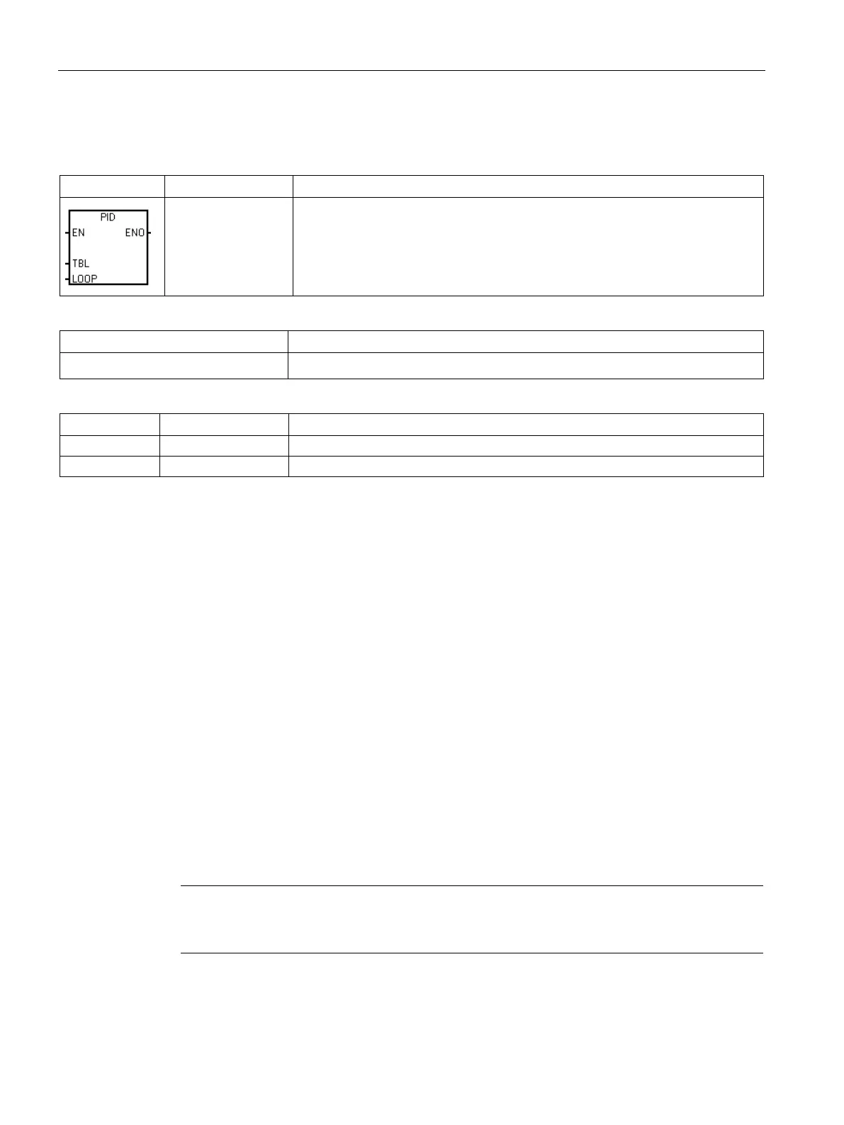
The PID loop instruction (PID) executes a PID loop calculation on the referenced
LOOP based upon the input and configuration information in Table (TBL).
Non-fatal errors with ENO = 0
• 0013H Illegal PID loop table • SM1.1 Overflow
The PID loop instruction (Proportional, Integral, Derivative Loop) is provided to perform the
PID calculation. The top of the logic stack (TOS) must be ON (power flow) to enable the PID
calculation. The instruction has two operands: a TABLE address which is the starting
address of the loop table and a LOOP number which is a constant from 0 to 7.
Eight PID instructions can be used in a program. If two or more PID instructions are used
with the same loop number (even if they have different table addresses), the PID
calculations will interfere with one another and the output will be unpredictable.
The loop table stores nine parameters used for controlling and monitoring the loop operation
and includes the current and previous value of the process variable, the setpoint, output,
gain, sample time, integral time (reset), derivative time (rate), and the integral sum (bias).
To perform the PID calculation at the desired sample rate, the PID instruction must be
executed either from within a timed interrupt routine or from within the main program at a
rate controlled by a timer. The sample time must be supplied as an input to the PID
instruction via the loop table.
Auto-Tune capability has been incorporated into the PID instruction. Refer to "PID loops and
tuning" (Page 467) for a detailed description of auto-tuning. The "PID Tune control panel"
(Page 476) only works with PID loops created by the PID wizard.
STEP 7-Micro/WIN SMART offers the PID wizard to guide you in defining a PID algorithm for
a closed-loop control process. Select the "Instruction wizard" command from the "Tools"
menu and then select "PID" from the "Instruction wizard" window.
Note
The setpoint of the low range and the setpoint of the high range should correspond to the
process
variable low range and high range.

 Loading...


