PLC concepts
4.2 Accessing data
S7-200 SMART
60 System Manual, 09/2015, A5E03822230-AC
The CPU stores information in different memory locations that have unique addresses. You
can explicitly identify the memory address that you want to access. This allows your program
to have direct access to the information. To access a bit in a memory area, you specify the
address, which includes the memory area identifier, the byte address, and the bit number
(which is also called "byte.bit" addressing).
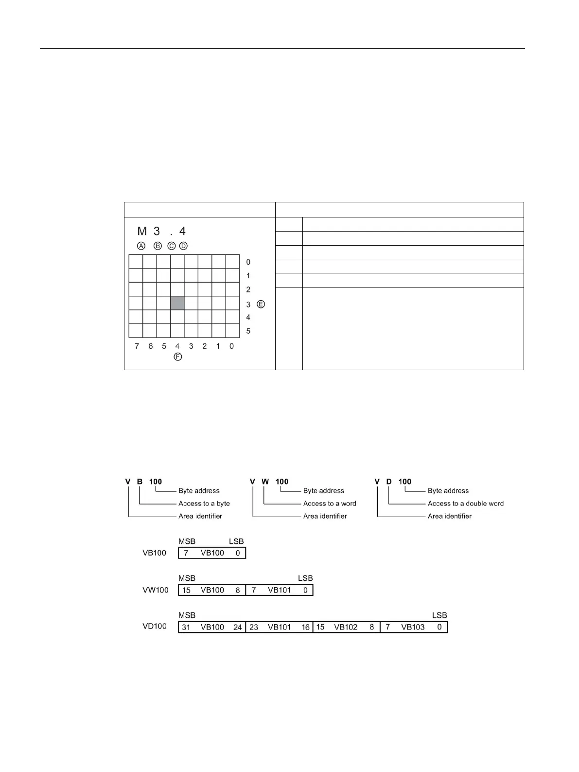
Table 4- 2 Bit addressing
Elements of a bit address
B Byte address: byte 3
Bit location of the byte (bit 4 of 8, bits numbered 7 to 0)
F Bits of the selected byte
In this example, the memory area and byte address ("M3") designates byte 3 of M memory,
with a period (".") to separate the bit address (bit 4).
You can access data in most memory areas (V, I, Q, M, S, L, and SM) as bytes, words, or
double words by using the byte-address format. To access a byte, word, or double word of
data in the memory, you must specify the address in a way similar to specifying the address
for a bit. This includes an area identifier, data size designation, and the starting byte address
of the byte, word, or double-word value, as shown in the following figure.
 Loading...


