PLC device configuration
6.1 Configuring the operation of the PLC system
S7-200 SMART
134 System Manual, 09/2015, A5E03822230-AC
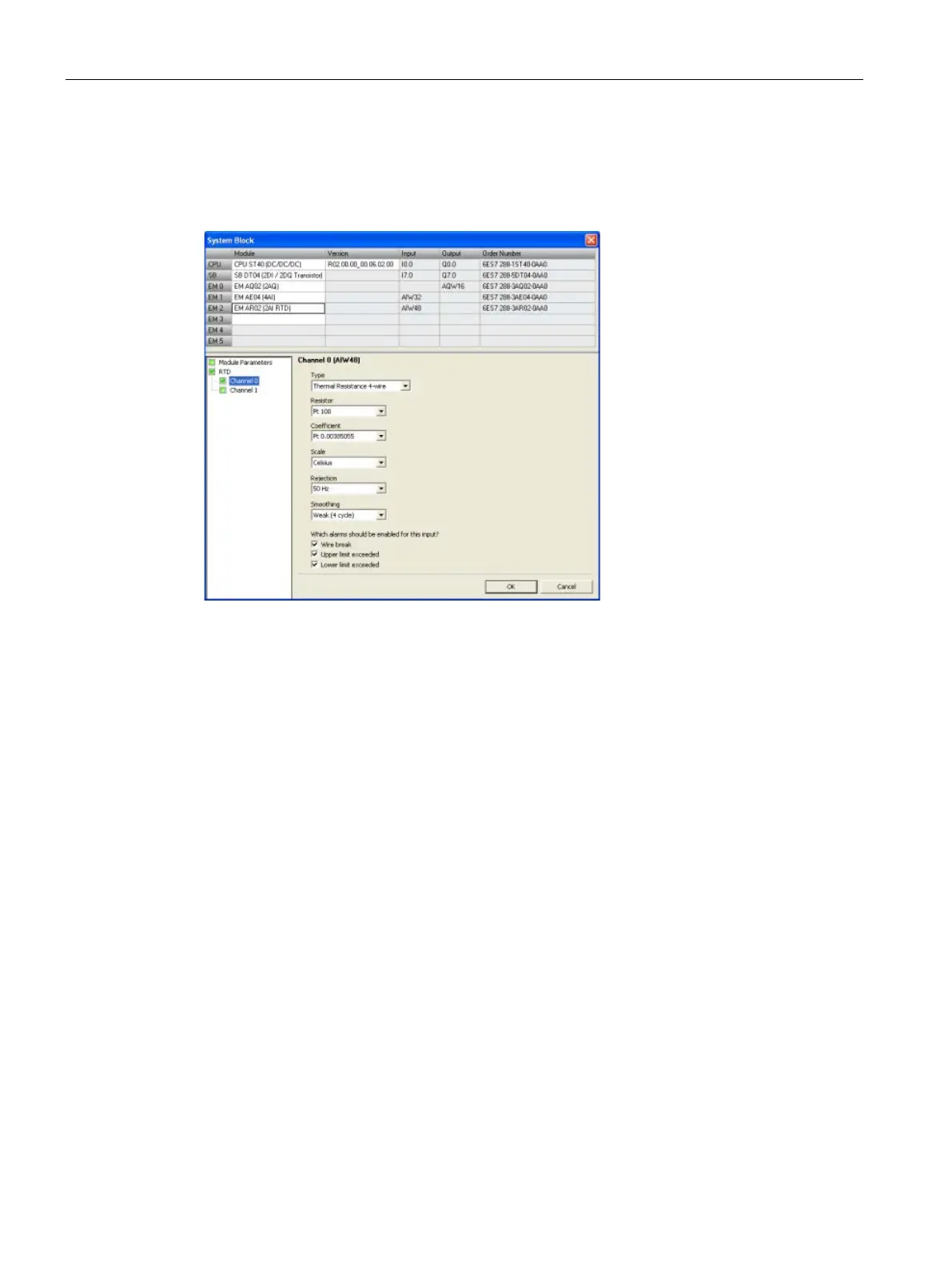
Configuring the RTD analog inputs
Click the RTD analog Input node of the system block (Page 115) dialog to configure options
for an RTD analog input module that you have selected in the top section.
The RTD analog input module provides a current at terminals I+ and I- for resistance
measurements. The current is fed to the resistance for measuring its voltage potential. The
current cables must be wired directly to the resistance thermometer/resistor.
Measurements programmed for 4-or 3-wire connections compensate for line resistance and
return considerably higher accuracy compared to 2-wire connections.
For each RTD input channel, you configure the type, choosing one of the following options:
● Resistance 4-wire
● Resistance 3-wire
● Resistance 2-wire
● Thermal Resistance 4-wire
● Thermal Resistance 3-wire
● Thermal Resistance 2-wire
 Loading...


