Program instructions
7.7 Pulse output
S7-200 SMART
System Manual, 09/2015, A5E03822230-AC
249
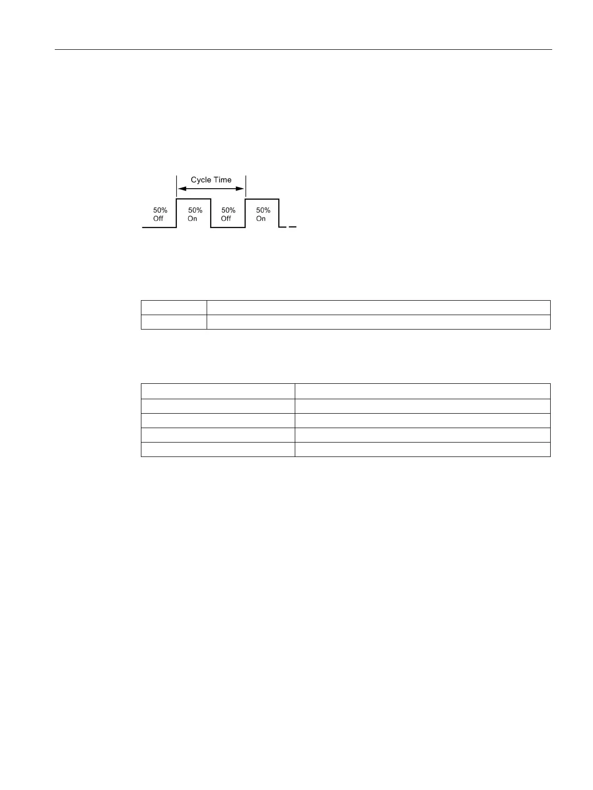
PTO provides a square wave with a 50% duty cycle output for a specified number of pulses
at a specified frequency. Refer to the figure below. PTO can produce either a single train of
pulses or multiple trains of pulses using a pulse profile. You specify the number of pulses
and the frequency:
Number of pulses: 1 to 2,147,483,647
Frequency:
– 1 to 100,000 Hz (multiple-segment)
– 1 to 65,535 Hz (single-segment)
Use the following formula to convert from cycle time to frequency:
where:
See the following table for pulse count and frequency limitations:
Table 7- 8 Pulse count and frequency in the PTO function
Frequency defaults to 1 Hz
Frequency defaults to 100,000 Hz
Pulse count defaults to 1 pulse
Pulse count > 2,147,483,647
Pulse count defaults to 2,147,483,647 pulses
The PTO function allows the "chaining" or "pipelining" of pulse trains. When the active pulse
train is complete, the output of a new pulse train begins immediately. This allows continuity
between subsequent output pulse trains.
Single-Segment pipelining of PTO pulses
In single-segment pipelining, you are responsible for updating the SM locations for the next
pulse train. After the initial PTO segment has started, you must immediately modify the SM
locations with the parameters of the second waveform. After you update the SM values,
execute the PLS instruction again. The PTO function holds the attributes of the second pulse
train in a pipeline until it completes the first pulse train. The PTO function can store only one
entry at a time in the pipeline. When the first pulse train completes, the output of the second
waveform begins, and you can store a new pulse train specification in the pipeline. You can
then repeat this process to set up the characteristics of the next pulse train. Attempting to
load the pipeline while it is still full results in the PTO Overflow bit (SM66.6, SM76.6, or
SM566.6) being set and the instruction being ignored.

 Loading...


