Program instructions
7.1 Bit logic
S7-200 SMART
158 System Manual, 09/2015, A5E03822230-AC
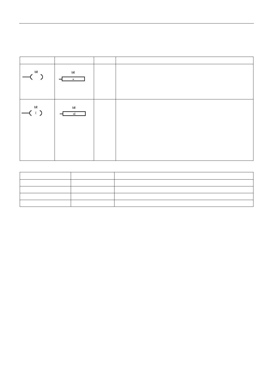
Coils: output and output immediate instructions
The Output instruction writes the new value for the output bit to the
process image register.
and
: When the output instruction is executed, the S7-200
turns the output bit in the process image register ON or OFF. The as-
signed bit is set equal to power flow state.
STL: The value on the top of the stack is copied to the assigned bit.
The Output Immediate instruction writes the new value to both the
physical output and the corresponding process image register location
when the instruction is executed.
and
: When the output immediate instruction is executed, the
physical output point (bit) is immediately set equal to power flow. The
"I" indicates an immediate reference; the new value is written to both
the physical output point and the corresponding process image register
address. This differs from the non-immediate references, which only
write the new value to the process image register.
: The instruction immediately copies the value on the top of the
stack to the assigned physical output bit and process image address.
I, Q, V, M, SM, S, T, C, L
I, Q, V, M, SM, S, T, C, L, Logic flow
Bit logic output examples (Page 163)

 Loading...


