Installation
3.3 Installation and removal procedures
S7-200 SMART
46 System Manual, 09/2015, A5E03822230-AC
Table 3- 4 Removing an expansion module
Follow the steps below to remove an expansion module:
1. Ensure that the CPU and all S7-200 SMART equipment are disconnected from
electrical power.
2. Remove the I/O connectors and wiring from the expansion module.
3. Loosen the DIN rail clips of all the S7-200 SMART devices.
4. Physically slide the expansion module to the right.
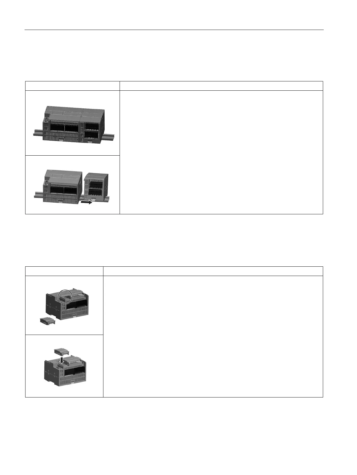
Installing and removing a signal board or battery board
Table 3- 5 Installing a signal board
Follow the steps below to install a signal board or battery board
1. Ensure that that the CPU and all S7-200 SMART equipment are disconnected from
electrical power.
2. Remove the top and bottom terminal block covers from the CPU.
3. Place a screwdriver into the slot on top of the CPU at the rear of the cover.
4. Gently pry the cover up and remove it from the CPU.
5. Place the signal board or battery board straight down into its mounting position in the
top of the CPU.
6. Firmly press the module into position until it snaps into place.
7. Replace the terminal block covers.

 Loading...


