Installation
3.3 Installation and removal procedures
S7-200 SMART
System Manual, 09/2015, A5E03822230-AC
47
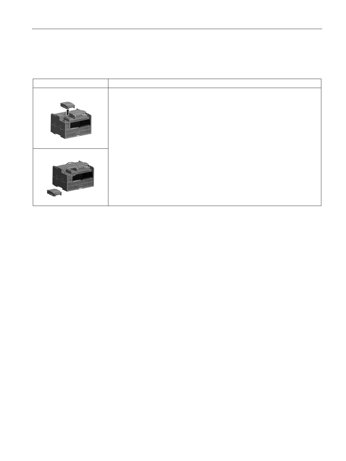
Table 3- 6 Removing a signal board or battery board
Follow the steps below to remove a signal board or battery board
1. Ensure that the CPU and all S7-200 SMART equipment are disconnected from electri-
cal power.
2. Remove the top and bottom terminal block covers from the CPU.
3. Place a screwdriver into the slot on top of the module.
4. Gently pry the module up to disengage it from the CPU.
5. Remove the module straight up from its mounting position in the top of the CPU.
6. Replace the cover onto the CPU.
7. Replace the terminal block covers.
Installing or replacing the battery in the SB BA01 battery board
The SB BA01 battery board requires battery type CR1025. The battery is not included with
the SB BA01 and must be purchased.
To install the battery, follow these steps:
1. In the SB BA01, install the new battery with the positive side of the battery on top, and the
negative side next to the printed wiring board.
2. The SB BA01 is now ready to be installed in the CPU. Follow the installation directions
above.
To replace the battery, follow these steps:
1. Remove the SB BA01 from the CPU following the removal directions above.
2. Carefully remove the old battery using a small screwdriver. Push the battery out from
under the clip.
3. Install a new CR1025 replacement battery with the positive side of the battery on top and
the negative side next to the printed wiring board.
4. Re-install the SB BA01 battery board following the installation directions above.

 Loading...


