Communication
8.5 PROFIBUS
S7-200 SMART
392 System Manual, 09/2015, A5E03822230-AC
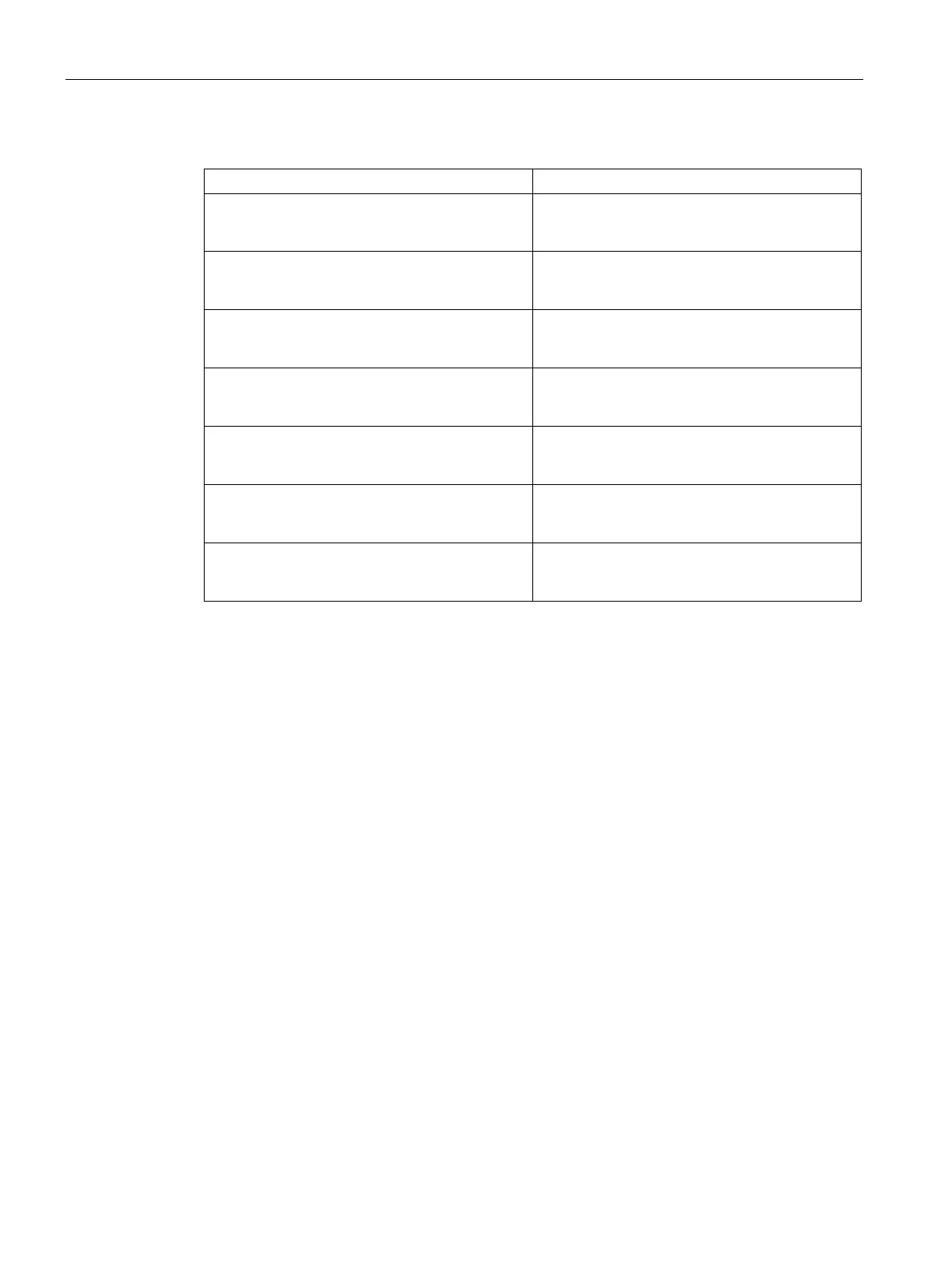
Table 8- 11 Module Definition List
Module
20
= " 4 Bytes In/Out" 0xF1
Module
21
= " 8 Bytes In/Out" 0xF3
Module
22
= " 16 Bytes In/Out" 0xF7
Module
23
= " 32 Bytes In/Out" 0xFF
Module
24
= " 64 Bytes In/Out" 0xC0, 0xDF, 0xDF
Module
25
= "122 Bytes In/Out" 0xC0, 0xFC, 0xFC
Module
26
= "128 Bytes In/Out" 0xC0, 0xFF, 0xFF
PROFIBUS DP communications to a CPU example program
An example program for the PROFIBUS DP module in slot 0 for a CPU that uses the DP port
information in SM memory is shown below. The program determines the location of the DP
buffers from SMW1402 and the sizes of the buffers from SMB1404 and SMB1405. This
information is used to copy the data in the DP output buffer to the process image output
register of the CPU. Similarly, the data in the process image input register of the CPU are
copied into the V memory input buffer.
In the following example program for a DP module in position 0, the DP configuration data in
the SM memory area provides the configuration of the DP device. The program uses the
following data:
V memory offset of outputs
Number of bytes of output data
Number of bytes of input data

 Loading...


