PLC device configuration
6.1 Configuring the operation of the PLC system
S7-200 SMART
144 System Manual, 09/2015, A5E03822230-AC
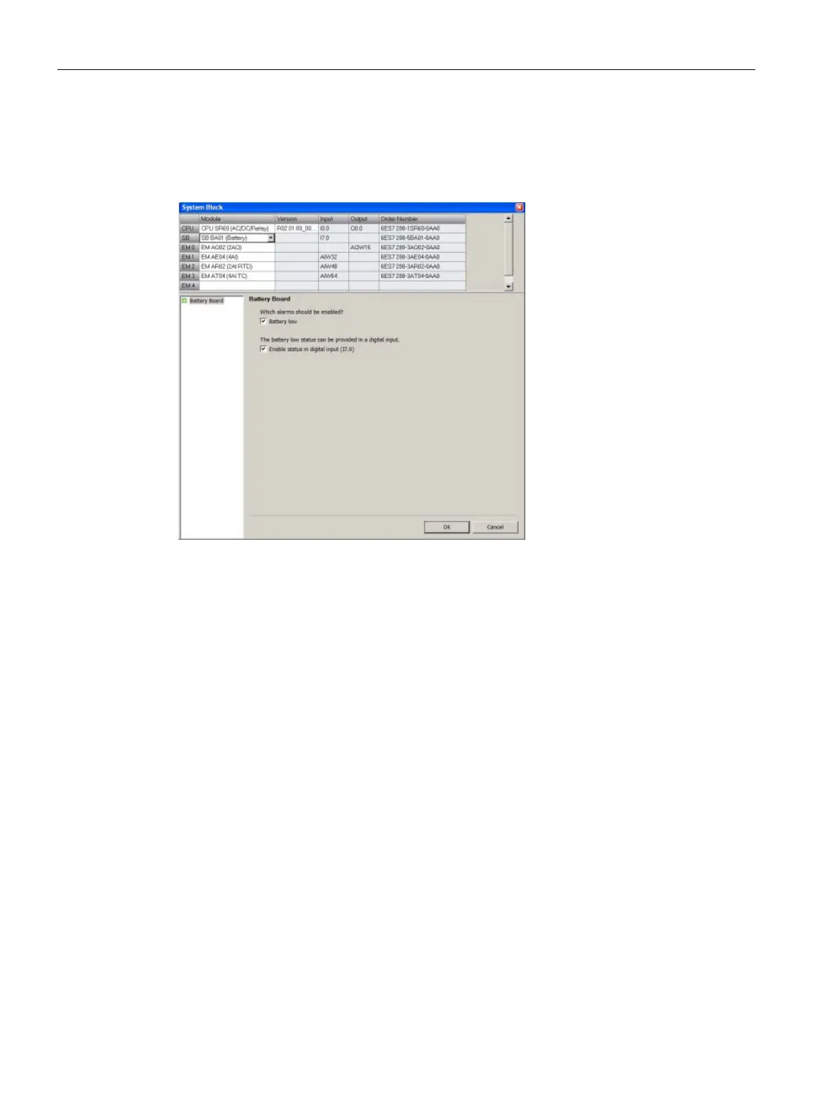
Configuring the BA01 battery signal board
Click the BA01 battery signal board node of the system block (Page 115) dialog to configure
options for a BA01 battery signal board that you have selected in the top section.
Enable bad diagnostic alarm
Click the “Enable bad diagnostic alarm” checkbox to trigger an alarm when the battery fails.
Enable status in digital input
Click the "Enable status in digital input" to enable a digital input to monitor the status of the
signal board.
Operation of the Battery (BA01) Signal Board
The battery signal board contains a red LED that provides the customer a visual indication of
the battery health. An Illuminated LED indicates a battery low condition.
The CPU automatically performs the RTC swap-over, battery test, and battery health LED
operation, whether or not the System block contains a configuration for the signal board.
The battery signal board System block configuration contains selections that allow the
customer to report the battery low state as a diagnostic alarm and/or to report the battery
state (1=battery low, 0 = battery OK) in the LSB of the configured image register input byte
for the device (for example, I7.0). The customer must select the battery signal board in the
System block configuration in order to gain access to the additional battery health reporting
options.

 Loading...


