Program instructions
7.1 Bit logic
S7-200 SMART
System Manual, 09/2015, A5E03822230-AC
157
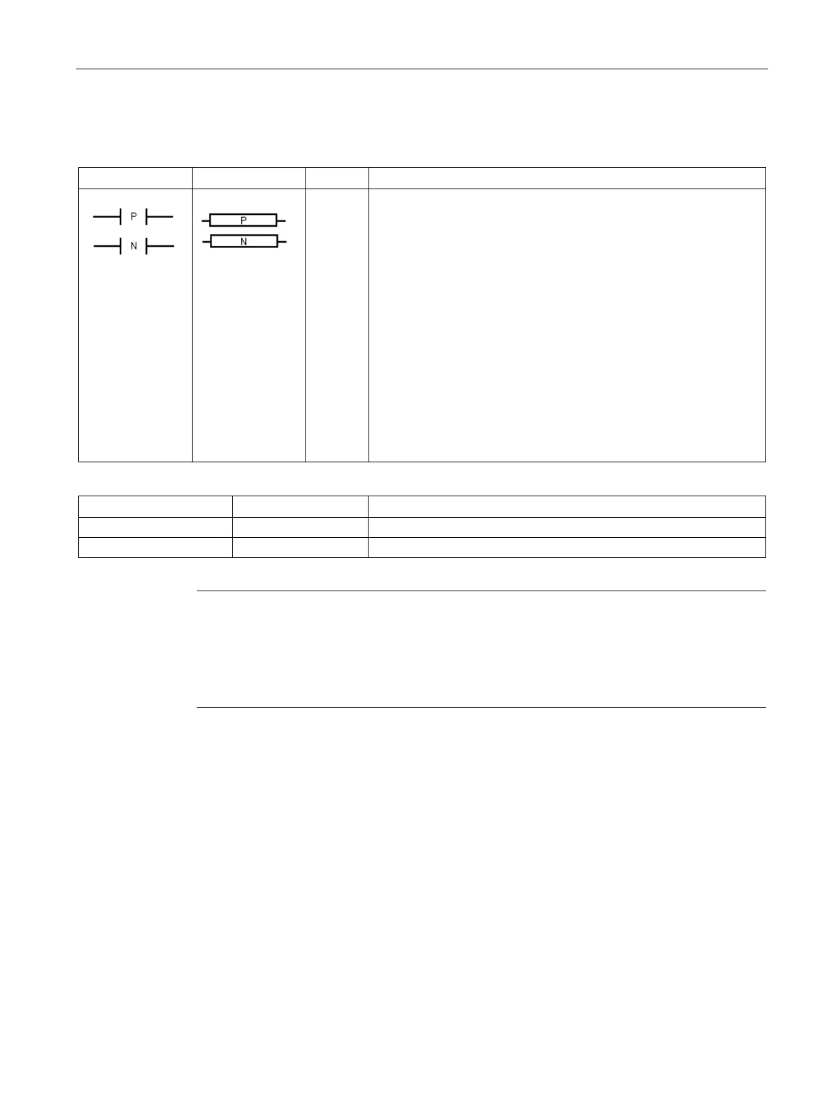
Positive and negative transition detectors
ED
The positive transition contact instruction (Edge Up) allows power to
flow for one scan for each OFF-to-ON transition.
The negative transition contact instruction (Edge Down) allows power
to flow for one scan for each ON-to-OFF transition.
S7-200 SMART CPUs support a combined total (positive and nega-
tive) of 1024 edge detector instructions in your program.
: Positive and negative transition instructions are represented by
contacts.
: The transition instructions are represented by the P and N box-
es.
: The positive transition is detected by the EU (Edge Up) instruc-
tion. Upon detection of a 0-to-1 transition in the value on the top of the
stack, the top of the stack value is set to 1; otherwise, it is set to 0.
The negative transition is detected by the ED (Edge Down) instruc-
tion. Upon detection of a 1-to-0 transition in the value on the top of the
stack, the top of the stack value is set to 1; otherwise, it is set to 0.
I, Q, V, M, SM, S, T, C, L, Logic flow
I, Q, V, M, SM, S, T, C, L, Logic flow
Note
Because the Positive Transition and Negative Transition instructions require an on
-to-off or
off-to-on transition, you cannot detect an edge-up or edge-down transition on the first
scan. During the first scan, the CPU saves the initial input state in a memory bit. On
subsequent scans, these instructions compare the current state and the state of the memory
bit, to detect a transition.
Bit logic input examples (Page 162)

 Loading...


