Program instructions
7.13 Program control
S7-200 SMART
300 System Manual, 09/2015, A5E03822230-AC
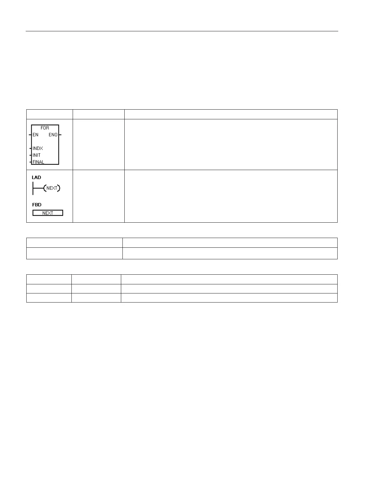
INIT, FINAL
The FOR instruction executes the instructions between the FOR and the NEXT
instructions. You assign the index value or current loop count INDX, the starting
loop count INIT, and the ending loop count FINAL.
The NEXT instruction marks the end of the FOR loop program segment.
Non-fatal errors with ENO = 0
• 0006H Indirect address
None
INDX INT IW, QW, VW, MW, SMW, SW, T, C, LW, AC, *VD, *LD, *AC
VW, IW, QW, MW, SMW, SW, T, C, LW, AC, AIW, *VD, *LD, *AC, Constant
Use the FOR and NEXT instructions to execute a program segment in a loop that is
repeated for the assigned count. Each FOR instruction requires one NEXT instruction. You
place a FOR-NEXT loop within a FOR-NEXT loop to a maximum nesting depth of eight.
If you enable a FOR-NEXT loop, the execution loop continues until it finishes the iterations,
unless you change the FINAL value from within the loop itself. You can change the values
while the FOR-NEXT loop is in the looping process. When the loop is enabled again, it
copies the INIT value to the INDX value (current loop number).
For example, given an INIT value of 1 and a FINAL value of 10, the instructions between the
FOR instruction and the NEXT instruction are executed 10 times with the INDX value being
incremented: 1, 2, 3, ... 10.
If the INIT value is greater than the FINAL value, the loop is not executed. After each
execution of the instructions between the FOR instruction and the NEXT instruction, the
INDX value is incremented and the result is compared to the final value. If the INDX is
greater than the final value, the execution loop is terminated.
For STL, if the top of the logic stack value is 1 when your program enters the FOR-NEXT
loop, then the top of the logic stack will be 1 when your program exits the FOR-NEXT loop.
 Loading...


