Programming concepts
5.3 Creating your user program
S7-200 SMART
96 System Manual, 09/2015, A5E03822230-AC
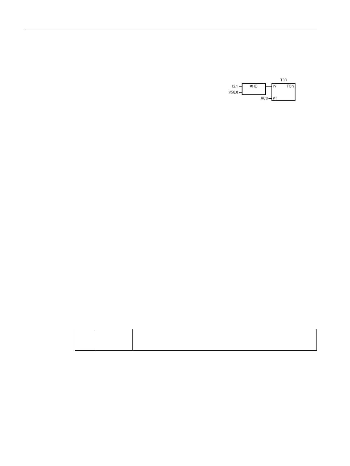
Features of the FBD editor
The FBD editor displays the program as a graphical re
p-
resentation that resembles common logic gate diagrams.
There are no contacts and coils as found in the LAD ed
i-
are equivalent instructions that appear as
FBD does not use the concept of left and right power rails; therefore, the term "logic flow" is
used to express the analogous concept of control flow through the FBD logic blocks.
The logic "1" path through FBD elements is called logic flow. The origin of a logic flow input
and the destination of a logic flow output can be assigned directly to an operand.
The program logic is derived from the connections between these box instructions. That is,
the output from one instruction (such as an AND box) can be used to enable another
instruction (such as a timer) to create the necessary control logic. This connection concept
allows you to solve a wide variety of logic problems.
Consider these main points when you select the FBD editor:
● The graphical logic gate style of representation is good for following program flow.
● You can always use the STL editor to display a program created with the SIMATIC FBD
editor.
Features of the STL editor
The STL editor displays the program as a text-based language. The STL editor allows you to
create control programs by entering the instruction mnemonics. The STL editor also allows
you to create programs that you could not otherwise create with the LAD or FBD editors.
This is because you are programming in the native language of the CPU, rather than in a
graphical editor where some restrictions must be applied in order to draw the diagrams
correctly. As shown in the following example, this text-based concept is very similar to
assembly language programming.
Table 5- 2 Sample STL user program
LD
A
I0.0
I0.1
// Read one input (I0.0).
// AND with another input (Q1.0).
// Write the value to an output 1.
The CPU executes each instruction in the order dictated by the program, from top to bottom,
and then restarts at the top.
STL uses a logic stack to resolve the control logic. You insert the STL instructions for
handling the stack operations.

 Loading...


