Libraries
9.3 Modbus library instructions
S7-200 SMART
System Manual, 09/2015, A5E03822230-AC
437
Table 9- 21 Required Modbus slave function support
Modbus slave function required
00001 – 09999 discrete outputs
Write Function 5 for a single output point
Function 15 for multiple output points
10001 – 19999 discrete inputs
30001 – 39999 input registers
40001 – 49999 holding registers
400001 - 465535
Write Function 6 for a single register
Function 16 for multiple registers
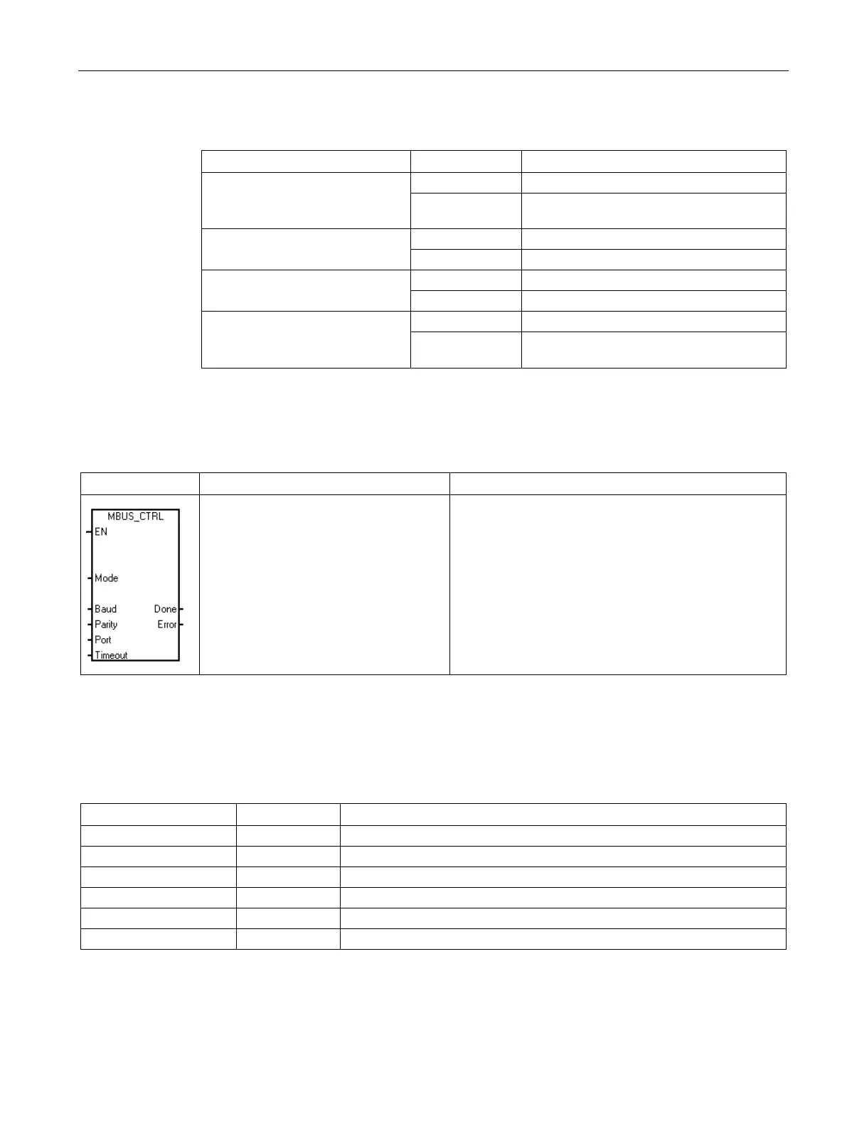
MBUS_CTRL instruction (initialize master)
Table 9- 22 MBUS_CTRL instruction
CALL MBUS_CTRL, Mode, Baud,
Parity, Port, Timeout, Done,
Error
The MBUS_CTRL instruction is used to initialize, monitor,
or to disable Modbus communications.
Before the MBUS_MSG instruction can be used, the
MBUS_CTRL instruction must be executed without er-
rors. The instruction completes and the Done bit is set
ON, before continuing to the next instruction.
This instruction is executed on each scan when the EN
input is on.
The MBUS_CTRL instruction must be called every scan (including the first scan) to allow it to
monitor the progress of any outstanding messages initiated with the MBUS_MSG instruction.
The Modbus master protocol will not operate correctly unless MBUS_CTRL is called every
scan.
Table 9- 23 Parameters for the MBUS_CTRL instruction
I, Q, M, S, SM, T, C, V, L
VD, ID, QD, MD, SD, SMD, LD, AC, Constant, *VD, *AC, *LD
VB, IB, QB, MB, SB, SMB, LB, AC, Constant, *VD, *AC, *LD
VW, IW, QW, MW, SW, SMW, LW, AC, Constant, *VD, *AC, *LD
I, Q, M, S, SM, T, C, V, L
VB, IB, QB, MB, SB, SMB, LB, AC, *VD, *AC, *LD
The value for the
input selects the communications protocol. An input value of 1
assigns the CPU port to Modbus protocol and enables the protocol. An input value of 0
assigns the CPU port to PPI system protocol and disables Modbus protocol.

 Loading...


