Programming concepts
5.3 Creating your user program
S7-200 SMART
System Manual, 09/2015, A5E03822230-AC
95
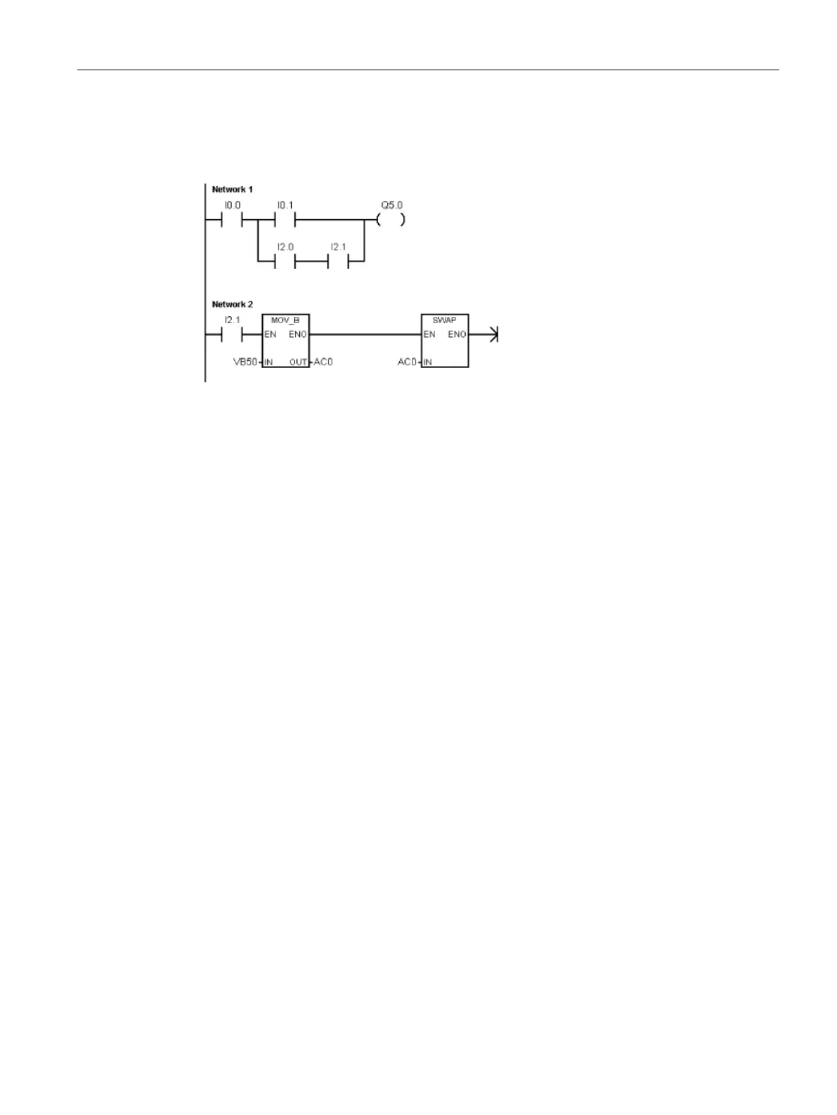
Features of the LAD editor
The LAD editor displays the program
as a graphical representation similar
to electrical wiring diagrams.
The LAD program emulates the flow of
electric current from a power source
through a series of logical input cond
i-
tions that in turn enable logic
al output
A LAD program includes a left power rail that is energized. Contacts that are closed allow
energy to flow through them to the next element, and contacts that are open block that
energy flow. The logic is separated into networks. The program is executed one network at a
time, from left to right and then top to bottom as dictated by the program.
The various instructions are represented by graphic symbols and include three basic forms:
● Contacts represent logic input conditions such as switches, buttons, or internal
conditions.
● Coils usually represent logic output results such as lamps, motor starters, interposing
relays, or internal output conditions.
● Boxes represent additional instructions, such as timers, counters, or math instructions.
Consider these main points when you select the LAD editor:
● Ladder logic is easy for beginning programmers to use.
● Graphical representation is easy to understand and is popular around the world.
● You can always use the STL editor to display a program created with the SIMATIC LAD
editor.

 Loading...


